
We have made a few posts showing off our 3D printers and some of the classes on 3D printing that we have done here at Digilent. Garrett Mace from macetech.com showed us some of the basics on how to use various 3D modeling software like AutoDesk Inventor, Autodesk 123D Design, OpenSCAD, MeshMixer, and SketchUp. Today, I’m going to introduce some of the basic modeling tools available in the free but robust Blender.
Although Blender isn’t as immediately user-friendly as some of the other software for first-time learners, after being shown some of the basic tricks available in Blender, I don’t think I will switch to a different 3D modeling software. To be fair, Blender does initially seem much more daunting than some of the other modeling software because it is capable of doing texture, lighting, animation, and physics in addition to the modeling portion (the only part I’m familiar with).
There are two main modes that I use in Blender: Object mode and Edit mode. Object mode is used for the “global” changes you want to make like choosing which object you want to work with, adding objects, and rotating, scaling, and moving the various objects that you have on the screen. Edit mode is for “local” changes that you want to make on a specific object such as various slices, extrusions, and other feature manipulations. You can easily switch between the two modes by pressing the TAB key.
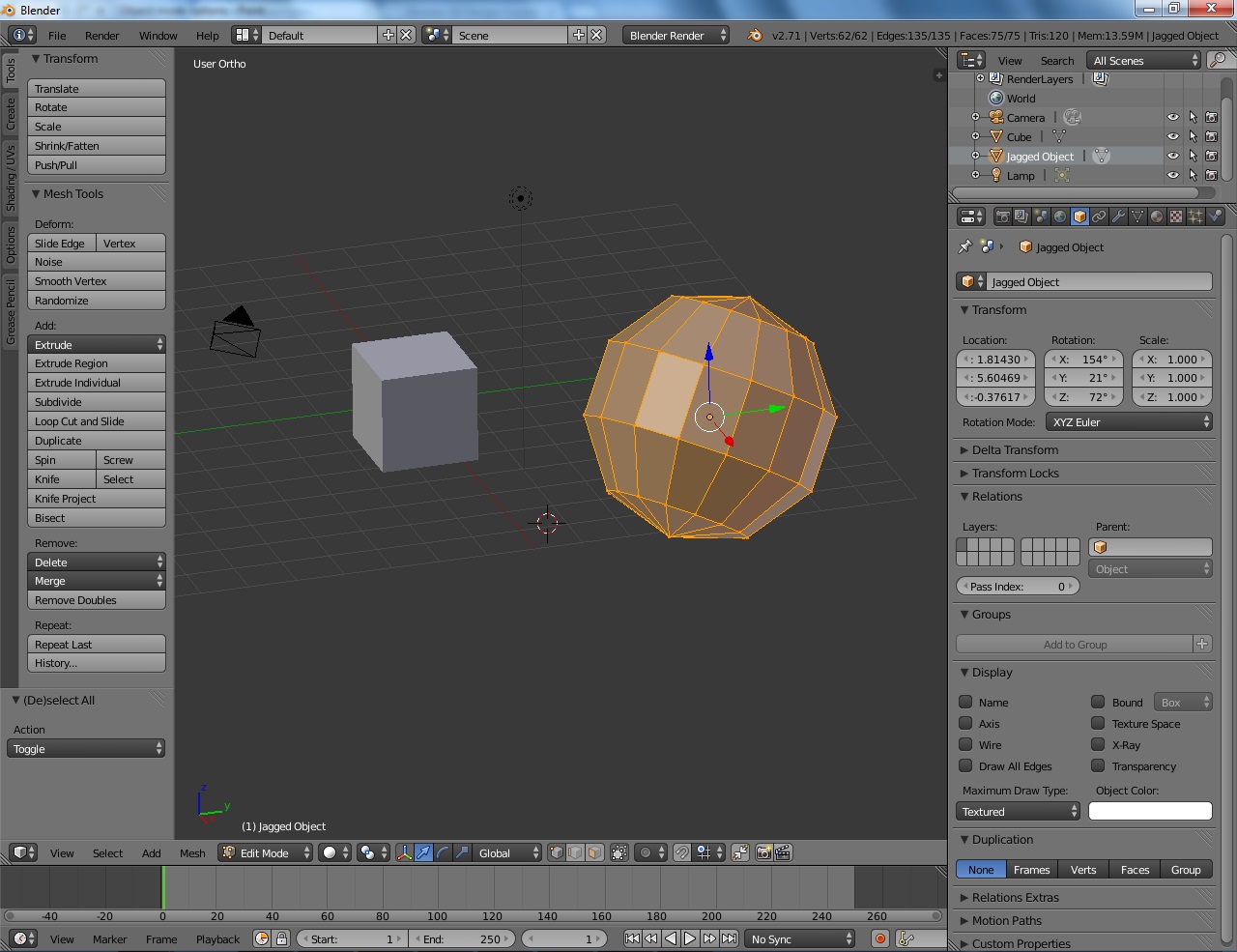
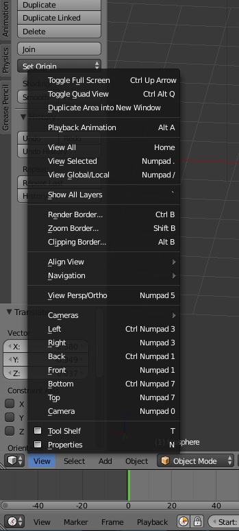
Unless you are far more visually gifted than I am (which is likely), moving the objects and, more importantly, the screen around effectively is a vital skill in 3D modeling. In Blender, this is actually a necessary skill, since many object manipulation tools, especially slicing, are perspective-oriented. I do the vast majority of my screen movement with the middle mouse button, which will rotate the screen around the current center of your visual perspective. I also use the scroll wheel by itself, or in conjunction with the SHIFT or CONTROL keys to zoom in and out, scroll up and down, or scroll left and right, respectively. The number keypad, or the View tab in the 3D View Editor at the bottom of the screen, will allow you to rotate your perspective in incremental values as well as having set default view angles along each of the coordinates’ axes.
Objects themselves can be moved in several different ways. After selecting an object in Object mode by right clicking on it, you may then continue to hold the right mouse button to freely move the object around the screen. Objects can also be moved in specific directions by left clicking on one of the three coordinate axis arrows and dragging the object to your desired location. If you accidently move an object to the wrong spot, you can always press CONTROL and the “Z” key simultaneously to undo your last action.
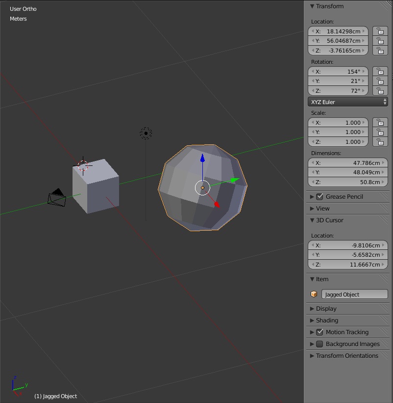
Realistically, though, it is rather hard to click and drag objects to the exact location and orientation that you want them to be in, considering that you only have a mouse to work with. However, if you press the “N” key, you will bring up the Properties Panel. This panel will let you specify the exact location, rotation angle, and even dimensions of your object; it’s pretty handy.
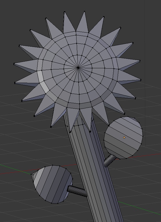
But while being able to move the screen and orient your objects the way you want them to is a vital skill, until you start manipulating an object’s shape, I would personally argue that it isn’t 3D modeling. Extruding is one of the popular manipulating techniques that is used in 3D modeling. What extruding does is stretch the edges of a particular feature to whatever distance you wish. The distinction here between the edges being stretched as opposed to the features themselves being extended is that if, for example, you extruded the face of a cube outward you would create a solid block, but rather a hollow extension.
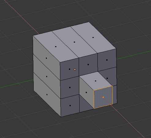
In fact, all of the objects in Blender are hollow objects. Although this may seem counter-intuitive towards 3D printing a solid object, the software that processes a 3D object to get it into the correct 3D printing format only looks at the outside of an object; it has no idea what is on the inside of the object. Instead, the 3D printer processing software will create an appropriate internal structure for the object to make sure that it structurally stable in it’s final form. That being said, you also want to make sure that your 3D model is watertight. This means that if you took your 3D model and had water on the hollow inside, there would be no place where the water can leak out. If there was such a place, the software that processes the model for 3D printing will see both the outside and “inside” of the object as the outside, potentially ruining the look of your print since the model would be processed incorrectly.
But back to extruding. To extrude a feature in Blender, go into Edit mode and select the feature you want by right clicking on it (or multiple features by holding the shift key and right clicking on multiple features). In the Tools tab on the Tool Shelf, there is an option to either “Extrude Region” or “Extrude Individual”. If not all of a feature is selected, both of these options are functionally the same. However, if all of the faces of an object are selected, “Extrude Individual” will extrude each of the faces in their orthogonal direction.
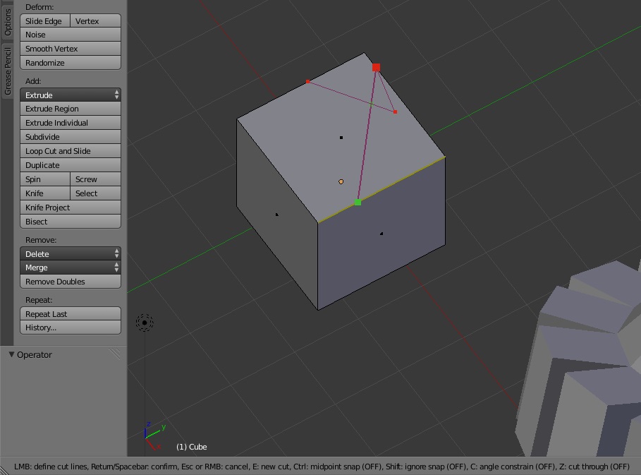
The final two manipulating techniques in Blender that I will talk about are the Knife and Knife Project tools. These are both slicing tools that are available in Blender to help create specific features on an object and can be accessed in the Tools tab on the Tool Shelf (again, in Edit Mode). The Knife tool allows you to select a variety of features that you want and then create a new edge along those features by confirming your cut with the SPACEBAR. You can then remove those features by selecting them and pressing the “X” key to delete the appropriate feature, or by selecting the feature and pressing the “P” key to separate that feature so that it is no longer associated with the object and can be freely moved and manipulated by itself.
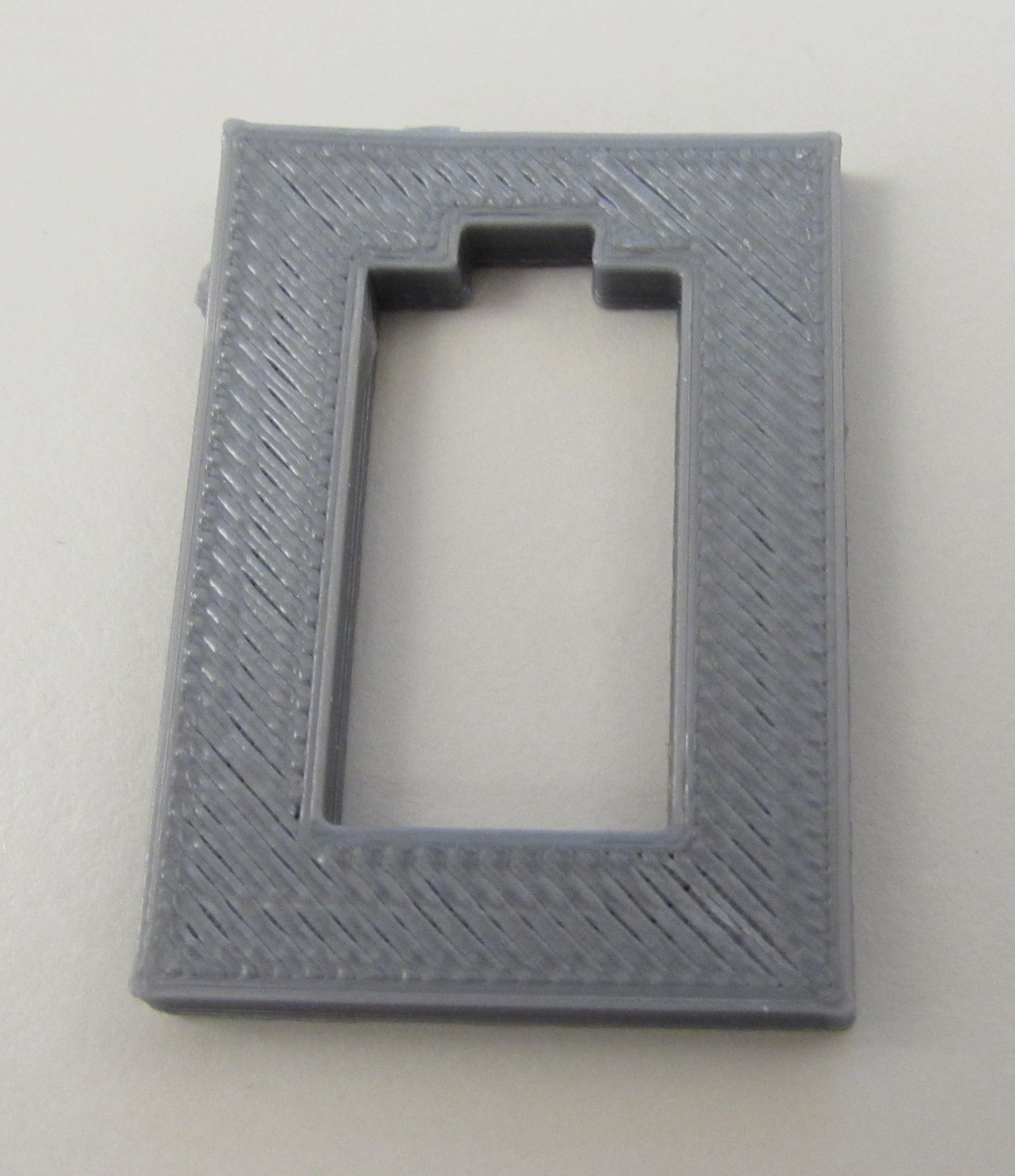
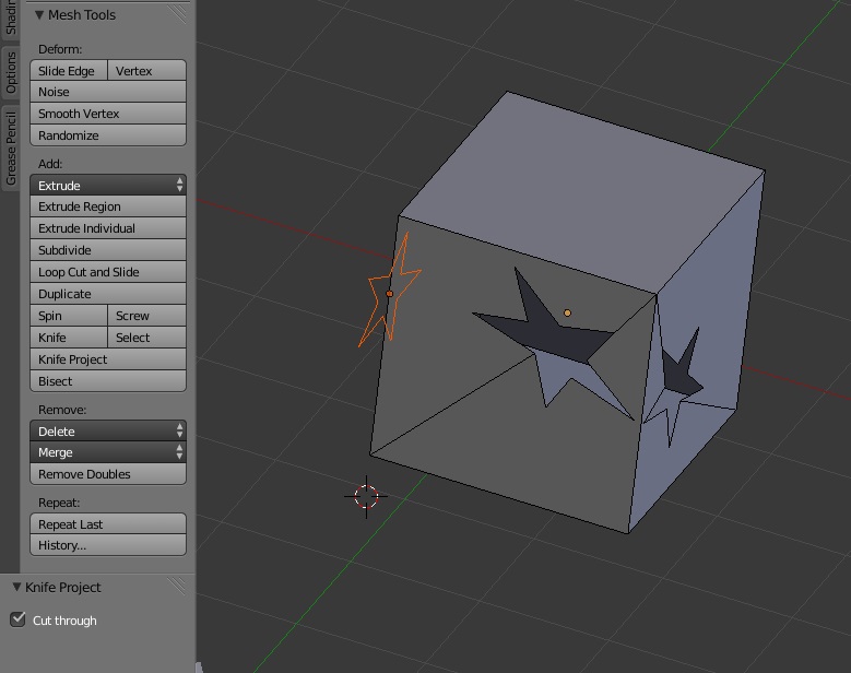
The Knife Project tool is the type of tool that allows you to cut the shape of an object into the surface of another object. To use this, you will need a flat object, such as a plane or a circle, to operate as the your knife, and another object that is to be cut. While in Object Mode, right click on the object you want to use as your knife and then hold the SHIFT key and right click on the object you want to be cut. Then go into Edit Mode and orient your screen so that your cut is placed where you visually want it to be and click “Knife Project” on the Tools tab. You may also choose to project your cut all the way through the object by checking the “Cut Through” box on the Knife Project menu on the left hand side of the screen. Be aware that after using the Knife Project tool that your object will likely no longer be watertight, so you may want to create some walls by selecting the vertices of your hole and pressing the “F” key to fill them in with a face.
Blender has many more techniques and tools that are available to further develop a 3D model. If you want to find out more about some of the basics of 3D modeling, check out my Instructable on 3D modeling with Blender.
To find out what other cool things the Digilent team is up to, keep checking back in here at the Digilent Blog!
For the issue of the screw holes lacking proper walls, try running the file through this service:
https://netfabb.azurewebsites.net/
I haven’t used blender before, but I run all of my STLs exported from Sketchup and it automatically creates a watertight file and fixes lots of other small issues with exported files!
-M Foreman
I’m genuinely impressed by the quality of your blog – it’s informative, engaging, and incredibly well-written!