
Who likes spy movies and TV shows? Come on, hold your hands up high! Yeah, you in the back, I know you do! What spy show would be complete without some kind of laser trip wire alarm system to keep the precious items safe? And what kind of agent worthy of the name Angus could actually be stopped by one?

http://thumbnails.cbsig.net/CBS_Production_Entertainment/CBS_Production_Entertainment/2009/ 02/27/Classic/MacGyver/Season_1/clips/Webclips/1000/633/CBS_MACGYVER_001_CLIP2.jpg
Even though they’re not the most secure setup and can be fairly easy to beat with some MacGyver skills, I still think the idea is pretty cool. So, I decided to build a fully functional analog laser trip wire circuit.
The idea comes from a property of LEDs that I have known about for some time but never used until now. I’m referring to the Mims Effect, conceptualized by the amazing Forrest Mims many years ago. Simply put, he figured that if an LED emits light at a fairly narrow bandwidth when forward biased with sufficient voltage and current, that same LED should absorb emitted light of the same wavelength and convert that light to usable, measurable power in the form of both current and voltage in the opposite direction.
Turns out, he was totally right, and we’ve been utilizing the Mims Effect for years. You know your T.V./stereo/air conditioner/you-name-it remote? If it was built after about 1980, odds are pretty good it uses an IR LED to transmit signals, which are then received by an IR sensitive diode in the device to detect those light pulses. (Fun side project – use your cell phone camera to see the IR pulses from an IR remote. Aim a remote at the camera lens and push any button. The sensor inside the camera is sensitive to IR light.)
Since the idea is really simple, I decided to go a little crazy with the rest of the circuit. After the LED comes on it activates a series of really simple but useful analog circuits. The first part amplifies and stabilizes the “ON” signal. Next, you need to latch the circuit on, regardless of what happens with the LED detector. Once on, a dual BJT oscillator flip-flops between two 555 timers. The 555’s are set up to generate two different audible frequencies, so as the first oscillator flip-flops between the two, you get a siren when the tones are fed through a small speaker.
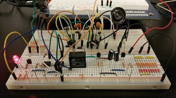
I also used the Digilent Electronics Explorer Board with the Waveforms 2015 software to capture some really good oscilloscope images of what was going on at various points in the circuit.
Go and check out my Instructable for more info and build instructions!