
A few months ago we announced that the Digilent Pmod Interface Specification would be updated and republished soon. Well here it is! Below you’ll find a quick overview of what has been changed.
First off, it’s important to point out that version 1.1.0 does not “break” any of the older Pmods. This means all Pmods following version 1.0.0 will still work with all Digilent system boards. The main change is an update of the I2C connection standard to bring enhanced compatibility to Pmods that use the I2C communication protocol.
If you’re familiar with Digilent Pmod boards, you’ll know that they are mostly 6-pin or 12-pin add-on modules designed to plug directly into 12-pin female host ports on our system boards. They use SPI, UART, I2C and GPIO to communicate. The I2C mechanical standard has always been somewhat of the odd one out as it used a 2×4-pin header which awkwardly did not plug directly into host boards as nicely as the others. You can do it, but it’s admittedly a bit of a hack. The new I2C standard is 6-pin and solves this pesky issue. See the table below for the pinout of the 1.1.0 I2C interface.
Pmod I2C Signal Specification
| Pin # | Signal | Direction | Alternate Signal |
| 1 | INT* | In | NC |
| 2 | RESET | Out | NC |
| 3 | SCL | In/Out | – |
| 4 | SDA | In/Out | – |
| 5 | GND | ||
| 6 | VCC |
SCL – Serial Clock
SDA – Serial Data
NC – Not Connected
*INT – Open drain interrupt signal from slave to master
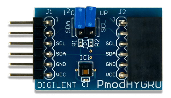
Now I2C will no longer be the odd one out of the Pmod family! We’ve already starting designing new Pmods to the above specification. For example, see the Pmod HYGRO below and the upcoming Pmod CMPS2 that will be released tomorrow. I2C Pmods are great for daisy chaining and will still maintain the ability to do so with the female 6-pin connector on the back (pictured below).
We have also updated the other interface pinout tables, such as SPI, UART, etc., creating more clarity, and added specifications for I2S protocol and H-bridge. And for even further clarity, we’ve updated the mechanical drawings so designing your own Pmod should be easier.
Visit the new spec on our Wiki!
I have used several of the PMOD units and have had little trouble using and programming them.
The one area I have had issues with is the location of the PMOD header. On the displays, you can’t mount them flush to the top of a case because the header is in the way. if it was soldered under the board, it would be much more useable. IMHO leaving the header un-soldered so I could be installed either direction would be best. I realize this could screw up the pin-out, but most of the 2×4 and 2×6 cables are broken out to a 1x on one end
I think that would be pretty cool as well to have the option use the Pmod port in a different way either for mounting on a different side of the board or even breaking out the individual pins in a more convenient fashion.
I imagine this would not be as appealing for some boards, especially for people want them to just work and not have to do anything besides program the board, so maybe there could be a specialized board either high end or low end (I don’t know if a professional or hobbyist would be more interested in this) with unmounted Pmod ports could be cool. Definitely niche, but a nice option.