
Welcome back to the Digilent Blog!
Today, we’re going to check out the last chunk of the input Pmods™ that Digilent offers. This set of inputs are slightly different than the inherent sensors that we saw last time. Although these Pmods are designed to give the system board information about the outside world, but this time you are their whole world. These tactile Pmods are designed so that they respond when you physically interact with them. It’s kinda like playing outside…in the comfort of your own home.
We’ll check out these Pmods starting with the straightforward, easy as flipping a switch Pmods and work our way up to others that are a little more fancy than that.
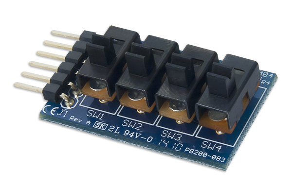
Not surprisingly, our first Pmod is the PmodSWT. This Pmod with its four switches is an easy way to get four distinct inputs that register as either “on” or “off”. There are no special timings, no additional commands, or extra processes that are needed to get this Pmod to work, just the ability to read the voltage state of one of the four input pins with a digitalRead() function. It is possible to get even more functionality by evaluating all four inputs as a group instead of individually to effectively quadruple your inputs from 4 to 16!
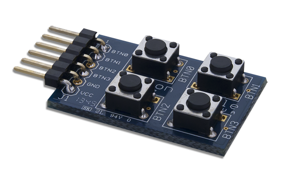
Next up we have the PmodBTN with its four pushbuttons. These buttons could also potentially be read in a group for 16 different options, but since pushbuttons pop back up after being pressed, it’s a little inconvenient to press multiple buttons at the same time. Despite this, the PmodBTN offers something that the PmodSWT does not; integrated debouncing. Buttons, along with other components that experience sudden changes in their on/off state (like switches) tend to “bounce” a little bit so that the electrical contacts inside of the button switch between touching and not touching a few times before settling down to a final state. When your microcontroller is running fast enough, such as the chipKIT™ line running at 80 MHz, it is possible for the microcontroller to notice all of these extra on/off states. A common example of this is setting the time on an alarm clock but having the numbers jump ahead in multiples when you only press the button once; it’s super frustrating. To fix this, the PmodBTN uses an inverting Schmitt trigger which only allows the output (and what the system board sees) to change once the voltage in the Schmitt trigger reaches the internal high or low threshold. Any bouncing that occurs won’t change the voltage enough to have the Schmitt trigger switch states, effectively cutting out all of the extra noise. It’s pretty helpful.
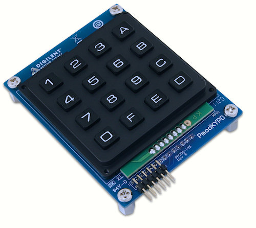
The PmodKYPD is for people who are of the belief that you cannot have too many buttons. With its keypad of 16 individual buttons, it’s easy to give the system board a variety of inputs without having to remember which combination is which like the PmodSWT. Although the buttons are labeled 0-F (0 to 16 in hexadecimal), we don’t have to be restricted to using those labels. After all, our system board will only be picking up the high and low voltage states of each of the data lines; it has no idea what is actually attached. Knowing this, I think it would be way more fun to use the PmodKYPD as a four-function calculator. You could even get super creative and have the PmodOLED show what you’re typing.
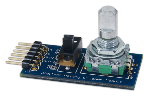
But perhaps you would like both a button and a switch? Check out the PmodENC! This Pmod features both a switch and an encoder that also doubles as a pushbutton. The encoder in this Pmod is designed like a camshaft that is able to press two different buttons. Taking advantage of the inherent design in a camshaft it is possible to have the system board know which way the shaft is rotating based on which button is pressed (or released if they were both pressed to begin with) first. It is also possible to potentially determine how fast the shaft is rotating based on the press/depress timings of the buttons, but there isn’t a way for the system board to know whether or not the shaft was rotating at a constant speed the whole time. Despite this, it is still very helpful in terms of knowing if the shaft has made a full 360 degree rotation or not.
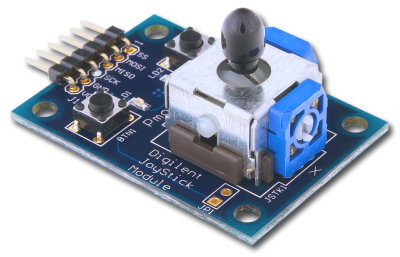
The PmodJSTK is what you are hoping it will be: a joystick. This Pmod, unlike the others that we have seen today, communicates with the host board not by GPIO, but through SPI. The reason for this is simply because it has that much information to transfer. Its two-axis joystick communicates its location in a 10-bit value for both the “x” and “y” directions. The 10-bit values are determined by a potentiometer for each direction; in the fully left (fully down) position, the potentiometer will report a value of 0 and in the fully right (fully up) position, the potentiometer will report a value of 1023. Both of these 10-bit words are transferred in the first four bytes of communicating with the host board. The 5th and final byte informs the system board about the status of the three pushbuttons: the two user buttons and the button that is on the joystick itself. With this easy interface, the PmodJSTK is a fun addition to any project.
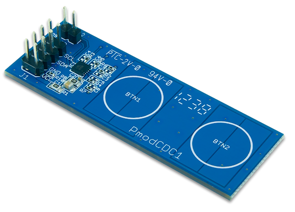
Next up is our capacitive touch sensor, the PmodCDC1. This is a fun Pmod (or at least I think so) that can tell whether or not you touched one of its two sensor locations. I find that the features you are able to code into it makes it especially cool. This chip can operate in both a fixed threshold or adaptive threshold mode. In terms of capacitance, this means that you are able to set upper and lower bounds in which the measured capacitance has to go above (or below) before the PmodCDC1 will send out an extra signal to the system board letting it know that there was a significant change in capacitance. The fixed threshold sets fixed upper and lower bounds while the adaptive threshold maintains the bounds to be a set percentage away from the average measured capacitance, which is nice since the ambient measured capacitance can change with temperature.
I personally prefer the adaptive threshold since it also uses a timeout feature. Normally, the upper and lower bounds will change slowly, but if your environment changes drastically, it will take a long time before the bounds average out to where they are supposed to be. With the timeout, the on-board capacitance-to-digital converter measures how long the incoming capacitance is outside its specified range. When the timeout limit is reached, the bounds are automatically readjusted to just the incoming data, ignoring all of the previous data so that you don’t have to wait for the adaptive boundaries to slowly change to what they need to be. In conjunction with communicating to the system board via I2C, this Pmod is a lot of fun.
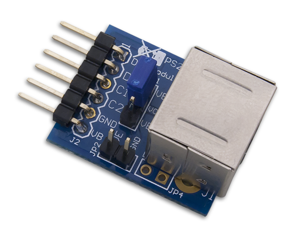
The PmodPS2 is a great module for anybody who wants to interact with their system board at any pace they wish. A PS/2 connector works by sending an “interrupt” and a series of data bits indicating which key(s) were pressed which the system board can act upon as soon as the interrupt is addressed. The benefit of a PS/2 port over a USB port for a keyboard, aside from the PS/2 requiring less work to process, is that the PS/2 is able to support NKRO (N-key rollover). This means that no matter how many keys are pressed at the same time, each key press will be received by the system board. This is different than a USB keyboard which typically can only support up to six keys being pressed at the same (depending which combination of keys you choose). Personally, I am a slow enough typer for a USB keyboard to have no issue in catching all of my keystrokes, but if you type much faster than I can or have a need for multiple key combinations, the PmodPS2 with its simple GPIO interface will work great!
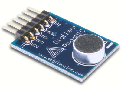
Our last, but not least, “tactile” Pmod is the PmodMIC. Although we don’t actually need to touch this Pmod, it does nicely act as a microphone, as the name so cleverly suggests. With its on-board ADC, the Pmod sends off 12 bits of data representing the outside noise through SPI. This particular microphone uses a dynamic range compressor; a device that adjusts the upper or lower decibel range (by lowering or raising the decibels, respectively) of an incoming audio signal. This technique allows an audio signal to be increased in volume without exceeding the decibel range on a recording device or speakers. In the case of our Pmod, it makes quieter sounds louder (in terms of having a larger 12-bit binary value being sent to the system board), while leaving louder sounds unaffected.
Although we have reached the sad moment where there are (currently) no more input Pmods to check out; the collection of 21 of these Pmods including ADCs, inherent sensors, and today’s tactile Pmods have all gotten a little bit of the spotlight. But don’t think we’re done yet!