
Recently I announced that National Instruments has released a set of example labs designed to show you how you can get the full use of your Analog Discovery 2. If you have since forgotten and want to review the summaries and mission of the seven labs, you can check out the original post here.
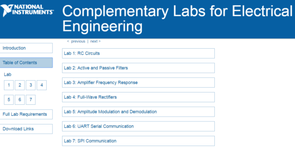
Over the next few weeks I’ll be covering each lab, the tools it uses, and concepts that can help you teach your students. In my previous post I went over Lab 1: Resistor-Capacitor Circuits. In this post I’ll be going over Lab 2: Active and Passive Filters.
Lab 2: Active and Passive Filters is designed to teach students about the characteristics of active and passive circuits. Students will learn how to build and analyze passive and active filters. The lab goes through the differences in their responses and how they can affect design choices.
This lab utilizes two sets of software, Multisim Live, and WaveForms 2015. Multisim live is a browser-based PC software that allows students to simulate their circuits from their tablet, smartphone, or computer, no matter where they are.
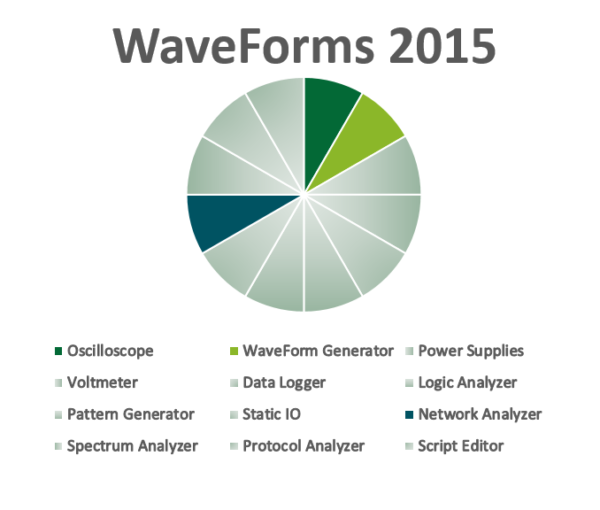
Waveforms 2015 is the software that drives the Analog Discovery 2. For this lab, students will use the Waveform Generators to provide the AC input, and Oscilloscope and Network Analyzer to discover the output. All of these tools are available to them on one device, the Analog Discovery 2!
For this lab students would need:
- An Analog Discovery 2
- Some resistors, capacitors, an opamp, a breadboard, and breadboard wires
- All of which can be found in the Analog Parts Kit
- A Multisim Live Premium account (Free for a limited time!)
- WaveForms 2015 (A Quick and Free Download)
Similar to Lab 1, Lab 2 goes through theory, simulation, and practical analysis.
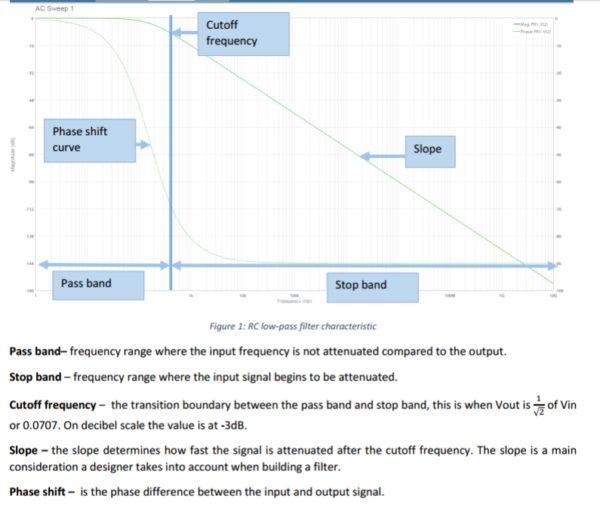
Students will first read about passive filters and their characteristics, such as cutoff frequency, phase shift, and more.
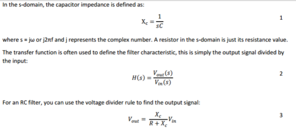
Next, the students are given a passive filter, the same from the last lab, and taught how to calculate the transfer function – from which they can get the magnitude and phase response.
They are then asked to build the circuit and simulate it. Then, using their knowledge to build a circuit with slightly different values for the characteristics, they are asked to verify it in Multisim Live.

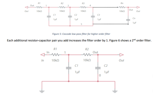
To build on the knowledge of transfer functions gained by a simple RC circuit, the lab reviews how to modify that circuit to build higher order filters, and how that changed the transfer function and filter behavior.
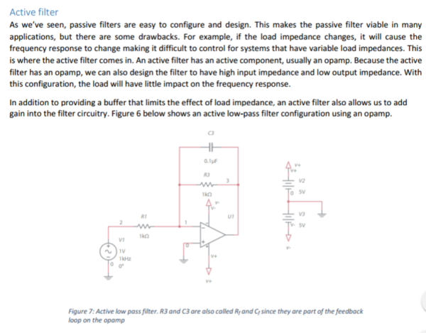
Then background on active filters is given, asking the students to go through the same exercises that they went through with passive filters.
Next, they go into practical exercises:
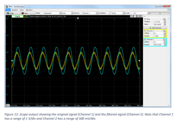
First, the students can build the 1st order passive filter, and use the arbitrary Function Generator on the Analog Discovery 2 to provide a sine wave with a higher and lower frequency component. They can then use the scope to show how the low-pass filter removes the “noise” from the signal. This demonstrates one of the practical uses of filters.
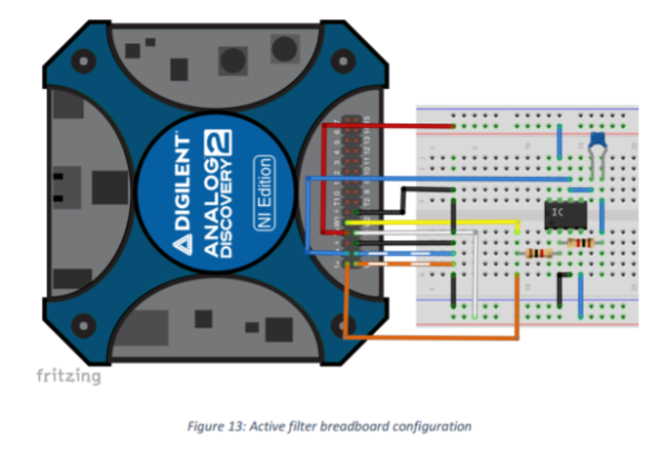
Next, they are asked to build the active filter and measure its frequency response using the Network Analyzer on the Analog Discovery 2. Using the Network Analyzer, they can swap out components and quickly re-plot the frequency response to gain an understanding of how each component affects the circuit behavior.
After the base knowledge is gained, the lab provides a challenge to students: explore the characteristics of specific filters, such as Butterworth and Chebyshev.
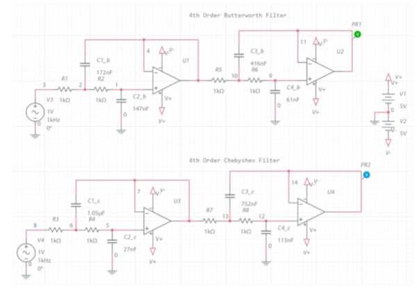
They can use Multisim Live to build and simulate the circuits, and then use the Analog Discovery 2 and WaveForms 2015 to examine their actual behavior. The Network Analyzer provides students with a quick way to verify their circuits behavior, and adjust components if needed for more of a rapid prototyping experience.
Stay tuned to the blog next week for Lab 3, or download and check out the labs yourself. If you are interested in the tools WaveForms has to offer, more information can be found on its Wiki Page.