
Want to run a power drift test at home?
“Any time you’re doing computing with something similar to a board like the Genesys ZU, it generates heat. That heat affects how efficiently power flows through wires or power rails. A computer’s designer needs to make sure that the power stays within specifications when the board you’re working with gets hot, so that it can continue managing the power and deploy the active heat dissipation it uses (fans etc.). So, I wanted to monitor the current measurement drift with temperature on one of the power management units (IC81, IRPS5401) on a powerful computing board. In this case, I used our new Genesys ZU.

- To monitor the current drift, I had to draw power using something external to the Genesys ZU board, so I used a small value power resistor with heatsink (shown in the lower-right side of the picture above) with a known large current (I used 10 Amps in my test) from VCC0V85_INT.
- While doing this, I also had to measure the actual current draw, using a digital multimeter in series with the power resistor (upper-right side of the picture);
- I used the same multimeter together with a thermocouple to monitor the temperature of the inductor on the VCC0V85_INT rail as it grew (white wire with blue stripes in the center of the picture
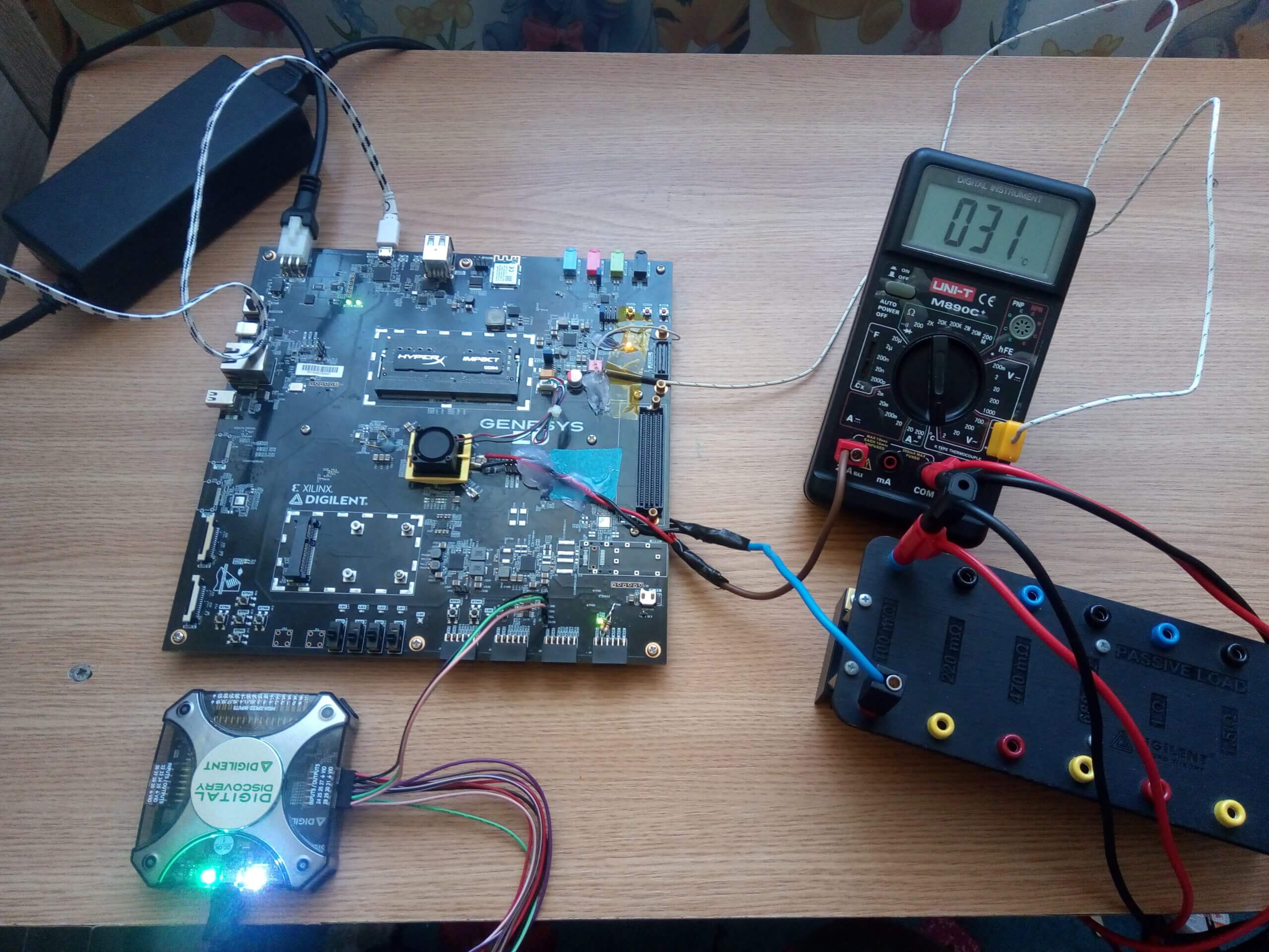
Also while doing this, I had to read back the current measured by IC81 itself. For this, I used a Digital Discovery connected to the I2C interface header on the Genesys ZU (J36): DIO24 to SCL, DIO25 to SDA, and a GND pin to the J36 GND pin.
To send the necessary commands to the IRPS5401 via I2C (actually PMBus, but it uses the same I2C lines) and to read back the current, initially I tried to use Waveforms in Protocol mode, but the I2C Master does not seem to have the “Repeated Start” functionality between Write and Read implemented. Therefore, I took a Python script example from the Waveforms SDK folder and modified it to suit my test (see below).
To run the Python script, you would need to follow these steps:
- Make sure the above described hardware setup is done;
- Make sure you have Python installed (I used Python 3.8);
- Make sure you have a UART Terminal software installed (TeraTerm, Termite etc.);
- Connect the Genesys ZU board to the computer via a Micro USB cable tied to J8 on the board;
- Power on the board;
- Open a UART terminal to the Platform MCU UART port (it is the largest numbered port of the two UARTs on Genesys ZU);
- Set the terminal to 115200 baud, 8 data bits, even parity, 1 stop bit;
- Disable I2C Communication between Platform MCU and PMUs, by sending the “1E0101” command (no “” signs) to the board using the UART terminal. As a check, you can then write “1F01” in the terminal and you should receive “01”.
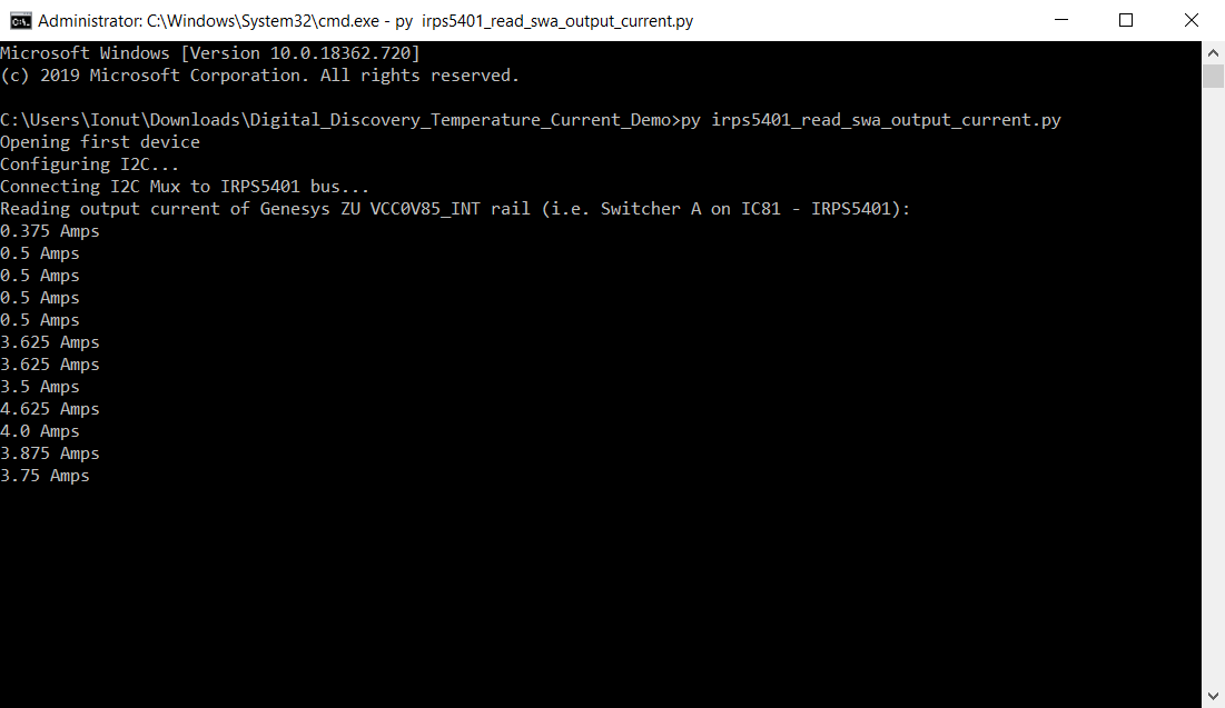
- Open a command prompt at the location where you downloaded the Python script. Type in “py irps5401_read_swa_output_current.py” and then Enter, to run the script.
- You should then see something like in the attached python_script_running.png. The script will run until you close the command prompt.
Users who have the Genesys ZU don’t necessarily have to draw current from the board using external means; therefore, they don’t necessarily need a multimeter, a power resistor or a thermocouple. If they have a Genesys ZU and a Digital Discovery/Analog Discovery 2, they can monitor the current drawn from the three IRPS5041 ICs on the board, one rail at a time, while running their own project on the board. I put some comments in the script so they can change the rail they monitor on the IRPS5401 (“the switcher”) and also to change the IRPS5401 they talk to.
Of course, you could also change the script to monitor all the rails on all the IRPS5401 ICs if you’d like to.”
To download the script for this test at home click here: irps5401_read_swa_output_current