
As with many open hardware standards, the Pmod Standard consists of a formal specification document as well as best practices. In order to ensure compliance and to use the Pmod name, all a designer needs to do is follow the Digilent Pmod Interface Specification. However, to ensure your Pmod or Pmod host platform can be used with as many other Pmod products as possible, consistency is key.
Contained in the spec, there is a lot of language like “should be” and “in general.” While we believe this is necessary to allow design flexibility and adaptation to unpredictable applications, we also want it to be easy to design to best practices for those who are interested in doing so for widespread support of the Pmod community. Furthermore, for those who may be interested in one day getting their Pmod sold on the Digilent website, best practices must be followed. The best practices followed by Digilent are listed below.
Best Design Practices
In no particular order, the following list enumerates the best practices for hardware design. This includes mechanical and electrical.
- The PCB should be 0.8″ wide.
In order to optimize the number of Pmod ports that can reasonably fit on a system board, the mechanical specification for the placement of Pmod host ports is 0.9″ center to center. Keeping the width of the Pmod PCB to 0.8″ allows for simultaneous utilization of all Pmod host ports. In other words, Pmods can comfortably sit side-by-side with 0.1″ of wiggle room in between. The below drawing illustrates this nicely.
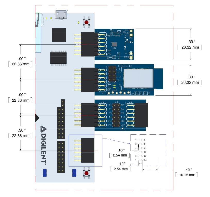
Of course many Pmods will be wider than 0.8″ by necessity. This is fine, but a good rule of thumb is to increase the length of a Pmod prior to increasing the width if possible. Again, the above drawing illustrates this concept.
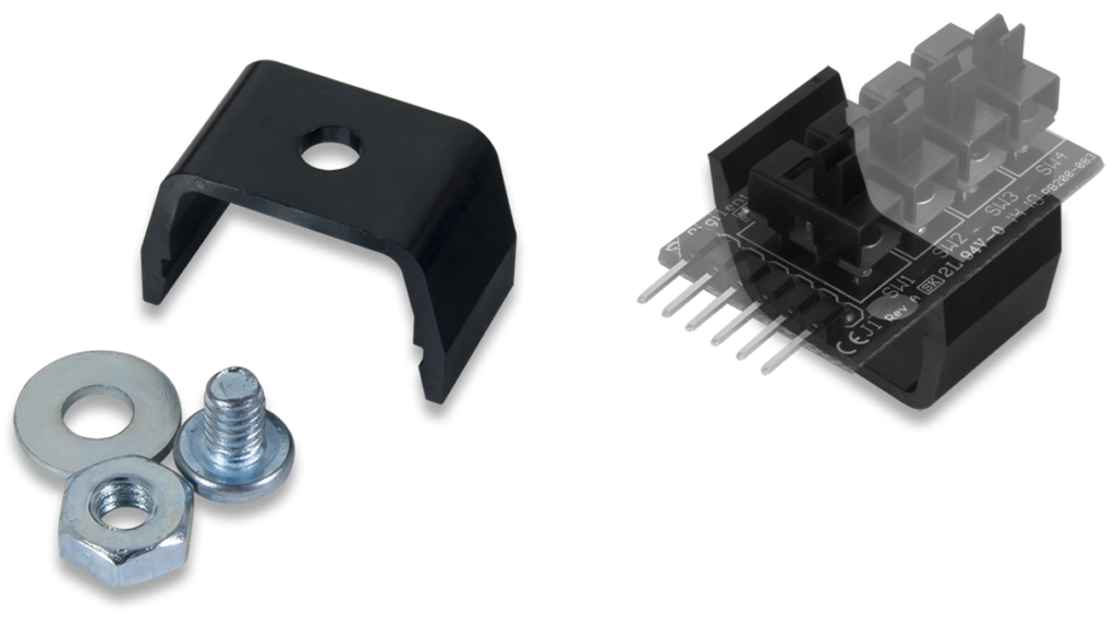
2. There should be >25 mil of clearance from the board edge to any components.
Digilent has designed the Pmod Clip for convenient mounting of Pmods. This can be useful for applications that require some rigidity, such as accurately measuring dynamic acceleration. To leave this mounting solution open to users, there must be >25 mil of clearance for the clip to properly latch the edge of the board. Although the Digilent Pmod clip was designed for the standard 0.8″ wide Pmod, it could easily be adapted to fit wider PCB’s. See the below image.
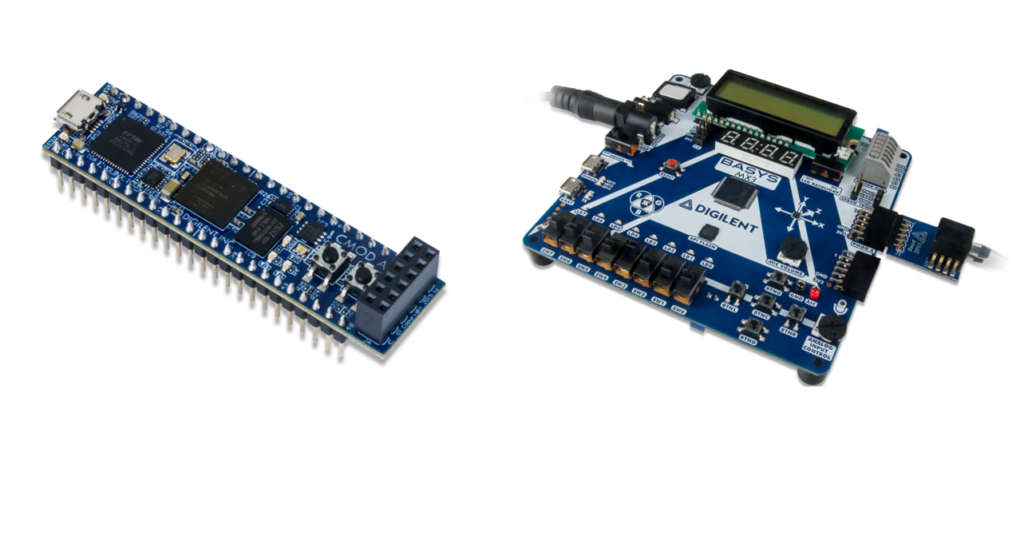
 3. All Pmod connectors intended for primary connection of Pmod boards to host platforms should be right angle connectors at board edge.
Straight male connectors or female host ports inboard from board edge are technically allowed by the spec, although it is discouraged for design of the primary connector. Sticking to right angle connectors will limit Pmod space requirements to the X-Y plane of the host platform as opposed to Pmods potentially sticking out in both the X-Y and Z planes simultaneously. It will also improve the visual branding, enhancing the recognizability of the Pmod or Pmod host as a member of the Pmod ecosystem. The below image illustrated right angle host ports on the right and a straight female host port on the left. The Cmod A7, on the left, is the only Digilent product with a straight female host port.
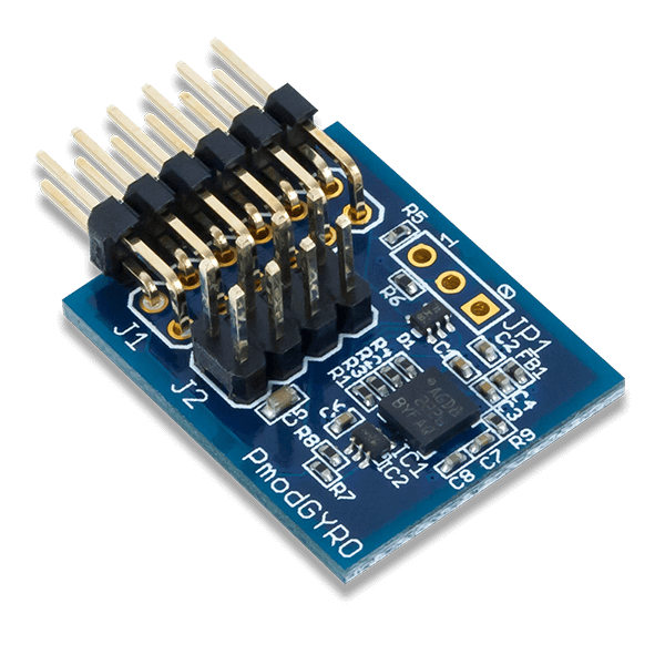
That being said, some Pmod boards benefit from a secondary connector. In this case, a straight male connector in-board from board edge is not discouraged. An example of this is the Digilent Pmod GYRO, which uses a standard 2×6 right angle male header for primary communication over an SPI bus, but also pins out an additional I2C header should the user prefer to communicate via I2C or to daisy chain the module using cables. The Pmod GYRO is pictured below.
4. Pmods should be designed to plug directly into system boards.
The use of cables should not be required for connection of any Pmod to a host platform. Care should be taken to ensure there is no mechanical interference preventing the direct connection of Pmods to hosts. This mostly applies to straight male connectors inboard from the board edge of a Pmod, if this header type is chosen for primary connection to a host platform. Although keep in mind that straight male connectors are discouraged for primary connection to begin with, as explained by number three above.
See the image below for an example of an old Digilent Pmod that requires the use of cables for connection to a host, i.e., what not to do if following best practices.
 5. Connectors should be on the top of the board.
To improve mechanical stability and ease of use, male Pmod connectors should be on the top of the Pmod. Pin 1 is always required to be on the far left of a 6-pin module and upper left of a 12-pin module.
6. I2C Pmods should include a female header to support daisy chaining.
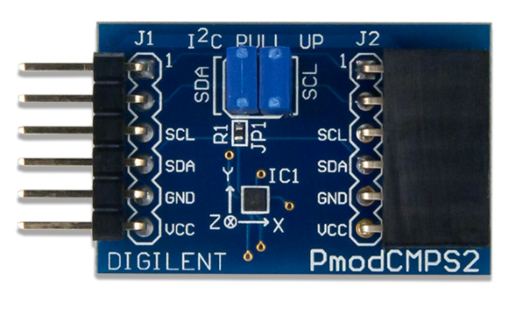
Digilent Pmod Interface Specification 1.1.0 and higher requires that I2C Pmods use the standard 6-pin male header. This is opposed to the original 1.0.0 spec which allowed 2×4-pin headers when using an I2C bus. Daisy chaining should be enabled via a female 6-pin header opposite the male header. This allows for daisy chaining through direct connection of Pmods or through the use of cable connections. If an additional male header was used in-board from board edge instead of the female header described, daisychaining would be restricted solely to the use of cable connections. See the image below for an example of the 6-pin female header used for daisychaining.
7. I2C pull-up jumpers should be on the top of the Pmod board.
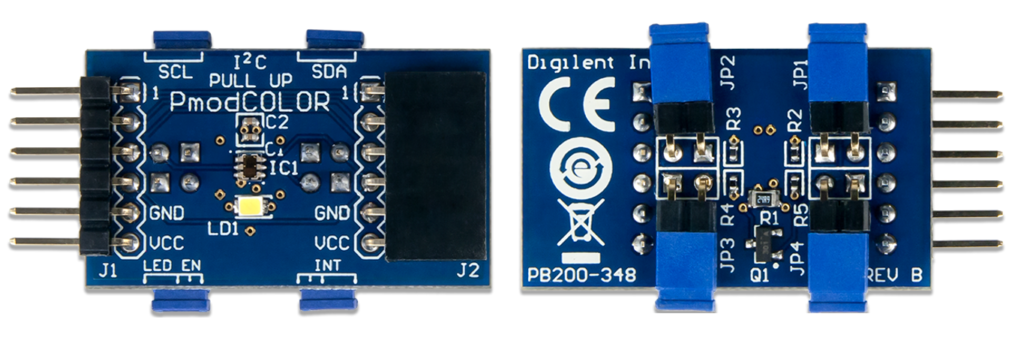
Digilent Pmod Interface Specification 1.1.0 and higher requires I2C Pmods to have onboard pull-ups that can be jumpered in and out. For mechanical stability, these jumpers should be on the top of the Pmod board if possible. In certain circumstances this may not be possible, as in the case of the Pmod COLOR colored light sensor which experienced measurement interference from the jumpers themselves. In a case such as this that requires the jumpers to be moved to the bottom of the board, they should be right angle jumpers to prevent the Pmod from sitting higher than the host platform on a flat surface. See the image below for an example using the Pmod COLOR.
8. Include jumpered pull-ups on system boards to be backward compatible with old I2C Pmods.
I2C Pmods that were designed in compliance with the original Digilent Pmod Interface Specification 1.0.0 were not required to have onboard pull-ups. Therefor, system boards designed to host I2C Pmods should include jumpered pull-ups for maximum compatibility with all existing I2C Pmods, should maximum compatibility be of concern to the designer. There is no way of knowing exactly how many legacy I2C Pmods exist in the world that do not have onboard pull-ups, however it is less than ten Digilent designed Pmods.
9. Assume LVCMOS 3.3 V logic conventions.
Digilent system boards use exclusively 3.3 V at the power supply pins on Pmod host ports. Operation at 5 V is allowed by the Digilent Pmod Interface Specification, but care should be taken to ensure 5 V will not damage the host’s input pins. For widest adoption, it is recommended to stick to LVCMOS 3.3 V logic conventions where possible.
10. Include ESD protection diodes and 200-ohm series resisters on standard Pmod ports.
Most Pmod host ports are standard ports and include ESD protection diodes and 200-ohm series resistors on the I/O pins in order to limit short circuit currents and driver conflicts. Some Digilent system boards have one or two “high speed” Pmod ports that exclude protection diodes and series resistors in exchange for higher switching speeds. If a Pmod host port is not intended for high speed use, it should include the protection diodes and series resistors. Most Pmods do not require the use of high speed ports.
11. Stacking multiple communication protocols on a single host port is encouraged, but a primary 12-pin communication protocol should be supported.
It is advantageous to design Pmod host ports (on host platforms) to support as many Pmod communication types as possible. When combining protocols on a single host port, at least one 12-pin Pmod communication type, as listed in the Digilent Pmod Interface Specification, should be supported as its primary type. Secondary 6-pin types may be supported for additional functionality. In other words, a host port should not be designed to support a 6-pin type on the top row of pins and a 6-pin type on the bottom row if it will exclude the use of 12-pin Pmods.
For example, if Pmod port A supports the 12-pin expanded SPI protocol as its primary type, it will by default also support all 6-pin SPI Pmods on the top row of pins. The converse may not be true. If it was designed specifically to support the 6-pin SPI protocol on the top row of pins and a different 6-pin protocol on the bottom row, it would not necessarily support 12-pin SPI Pmods by default. Therefor it is wise to support at least one 12-pin type. It may then be possible to support an additional 6-pin type, such as I2C, on the bottom and or top row of pins.
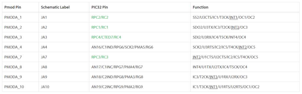
The example pinout table below is from a Digilent microcontroller board. The primary 12-pin communication types supported are expanded SPI, expanded UART and expanded GPIO, or types 2A, 3A and 1A respectively. In addition, 6-pin UART is enabled on the bottom row.
Remember that the above 11 bullets are best practices for Pmod design, but not necessarily requirements for compliance and use of the Pmod name. There will be cases where design restrictions require some of these best practices to be broken. Some of the examples given above even illustrate cases in which Digilent has broken best practices. However these are exceptions to the rule and care should be taken to avoid making such exceptions wherever possible. It is recommended to read the Digilent Pmod Interface Specification in its entirety for all compliance requirements, then cross reference the requirements with the best design practices.
For any questions or comments, please use the comment section below or visit the Digilent Forum!
This is a well made blog post explaining the heart behind the Digilent Pmod Interface Specification. Thank you for sharing it.
I disagree with on of the spec’s
# 5. Connectors should be on the top of the board.
This does not make for a good board on displays or other boards that are for user interface like joysticks or buttons. Having the connectors on the top of the board make it very hard to mount into a box to make nice looking display. the joystick would also be better if it was easier to mount. Since the pmod display boards ( except one ) are larger the the 0.8″ anyway it might be nice to see them with the connectors on the bottom and some mounting holes.
Just my 2 cents.
Hi Bill,
Thanks for the feedback. I think the heart behind the top of the board sentiment is that the right angle headers that are used on all of the Pmods are able to plug into the Pmod ports that are present on a large number of Digilent boards.
On the idea of the connectors being on the underside of the board, were you imagining they are still using a right-angle header? I do agree that having the connectors on the top-side can detract from the visual side of things, especially for larger modules that are only made even bigger by having to dedicate physical space to the connector sticking out the top of the board.
James –
Right angle header are fine.
The board size in NOT why I would put the headers on the bottom, It is the FUNCTION of the board. Having a display that has wires that are near or above the plane of the display makes it harder to mount and use. Same with the larger joystick (Pmod JSTK2)
If the idea is to only use the parts to prototype things – I guess it is ok.
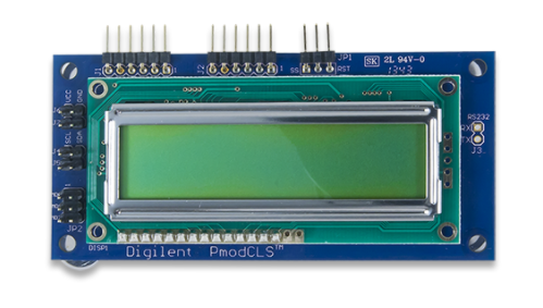
If on the other hand you want to use the parts to produce a small number of items, having the connectors on the top is counter to its function. I have used the Pmod OLED and Pmod CLS in projects. When using the OLED display I could not come up with a way to mount it in a box that allowed a good viewing. On the CLS unit I moved the header to the bottom so I could mount it in a box.
In design, form should follow function. If the function does not require access for viewing or touching (pushing buttons, etc) then no big deal.
If the function is for viewing or touching then make the unit so that it can be mounted to allow for viewing and touching.
As far as the statement: “top of the board sentiment is that the right angle headers that are used on all of the Pmods are able to plug into the Pmod ports” can you show me a photo of the Pmod MTDS hooked up to a board? Now, how do you put that in a box to make it look good?
Bill