
In one of my first circuits courses, the professor’s favorite words of advice were to “keep calm and remember KCL, KVL, and Ohm’s law.” With these three concepts, just about any electrical circuit can be analyzed and understood. Granted, things get a little more complicated when you add concepts like inductance and capacitance, but KCL, KVL, and Ohm’s law form the foundation of all circuit analysis. Brandon mentioned Ohm’s law in his blog post on how to choose a resistor for your design, so I will only be discussing KCL and KVL.
We’ll start with the simple question– what are they? KCL stands for Kirchhoff’s Current Law, and KVL stands for Kirchhoff’s Voltage Law. These two concepts are used to determine the current and voltage levels at relevant areas of interest within a circuit. They were first proposed by a German physicist, Gustav Kirchhoff, in 1845. Let’s talk about KCL first.
Specifically, KCL states that the sum of currents flowing into a given node is equivalent to the sum of currents flowing out of that node. Check out the picture below.
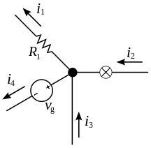
In the picture you can see that there are four relevant currents: i1, i2, i3, i4. Reiterating KCL, the sum of currents flowing into a given node is equivalent to the sum of currents flowing out of that node. In the image above, i2 and i3 are flowing into the node while i1 and i4 are flowing out of the node. This produces the equation i2 + i3 = i1 + i4. This concept can be used to solve for unknown currents when analyzing an electrical circuit.
Now on to KVL. KVL states the the sum of voltages around a closed loop equals zero. That being said, around the closed loop of a circuit, the sum of any “positive” voltages you encounter will equal the sum of any “negative” voltages you encounter. The figure below should help clarify this statement.
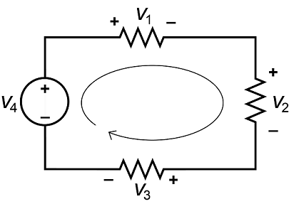
In the image above, note the positive and negative signs of each voltage and the direction of the arrow of our loop. Following the loop around the circuit, you would come across the positive voltages v1, v2, and v3 and the negative voltage v4. This yields the equation v1 + v2 + v3 – v4 = 0, or v1 + v2 + v3 = v4. This is reasonable because we would expect that the voltage around the entire circuit is equal to the voltage of the power supply v4. This concept is helpful in finding unknown voltages in an electrical circuit.
It should now be clear how KCL and KVL are important tools in the analysis of electrical circuits. For more specific examples on how these concepts are applied in the real world, check out the Digilent Learn site for KCL and KVL projects.