
Welcome back to the Digilent Blog!
Some of the Pmods, such as the PmodOLED and the PmodCLP, need a higher operating voltage to run their screen than is normally supplied by system boards. This predicament could be solved by using an external power supply to power the screens, but that can get pretty inconvenient especially if you want your project to be portable. A slightly easier method that does not require a power supply is a boost converter circuit.
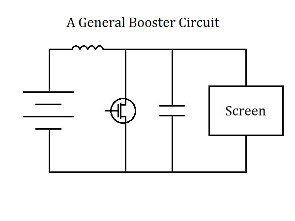
Boost converter circuits are a great way to increase the amount of voltage coming from your power source without drastically changing the wattage of your project. The main components that allows a boost converter to work provide the higher voltage is an inductor and a MOSFET switch. For those of you who might not know, inductors are a type of electronic component that are able to store energy. Unlike capacitors, which store energy in an electric field, inductors store energy inside of a magnetic field that is created when current flows through a coiled wire.
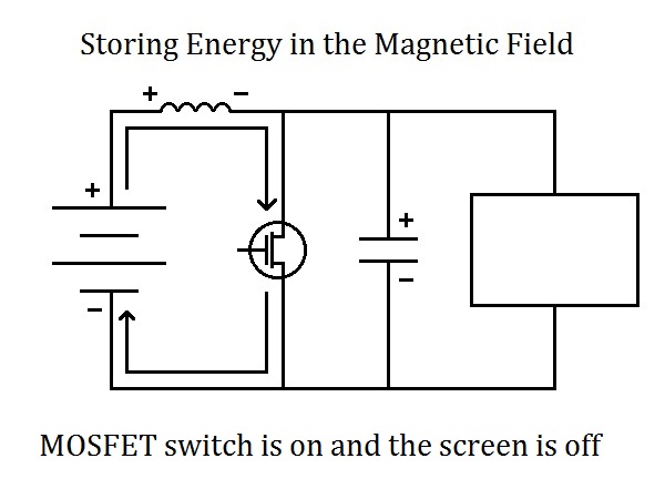
When the switch is driven “on”, a short circuit is created so that current only flows through the inductor and then back to the “ground” of the source of power. As mentioned earlier, when current is flowing through the coils of a conductor, energy is used to create a magnetic field around the conductor. This magnetic field creates a voltage differential across the inductor that opposes some of the electromotive force (e.m.f.) produced by the power source.
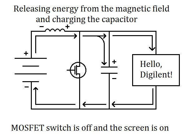
When the switch is turned off, this short circuit is broken, allowing current to flow to both the load (like a OLED screen) and a capacitor. Because of this load and the nature of Ohm’s Law (V = I*R), the increased resistance means that less current is able to flow from our power source through our project. However, because of that fact that energy is conserved (first law of thermodynamics), the current cannot just suddenly drop to a lower value because that would imply that some of the energy was destroyed. Consequently, what happens is that the magnetic field that had been created with the short circuit now starts to be destroyed. As it shrinks, the voltage differential across the inductor that had opposed the e.m.f. flips its polarity so that it is now adding to the voltage produced by the power source.
This additional boost in voltage (hence a boost converter circuit) accomplishes two things. The first is that with the higher voltage (of which the screen required in order to operate), the first law of Thermodynamics is now obeyed since the power flowing through our circuit is maintained so that no energy is inadvertently destroyed. This is because power is equal to the product of voltage and current; even though our current decreased because of extra resistance in our circuit, the voltage was increased with the decaying magnetic field, allowing the power to remain both continuous and differentiable.
The second accomplishment is that the capacitor that is in parallel with the circuit (or in our case, screen) simultaneously receives the higher voltage energy at the same time as the screen. Because of this, when the MOSFET switch is turned back “on” to re-energize the magnetic field the capacitor is able to provide the same higher voltage energy to the screen, effectively allowing the screen to receive a relatively constant supply of power.

Booster circuits aren’t only used for running a screen from your chipKIT board though. They are also commonly used in electric cars that might need 500V to operate but only carry enough battery cells to produce 200V. It’s a pretty handy circuit!
induced emf should oppose the supply voltage.
how come the load voltage increased?
Hi raj,
The key here (and I agree that I was not very clear about this in my post) is the switching of the MOSFET. When the switch is turned on, the induced emf does indeed oppose the supply voltage, but when the switch is turned off, the main power starts to power the display (rather than flowing through the switch) and the emf that did exist now flips in polarity and consequently also adds its previously stored power to the display as well, creating the higher voltage for the display.
The switching is internal for the Pmod OLED and Pmod CLP so the switching is set to the needed rate to create the needed voltage by the display.
Let me know if you have any more questions!
Thanks,
James Colvin