
 Announcing the addition of the Pmod COLOR to the Pmod sensor family!
Description
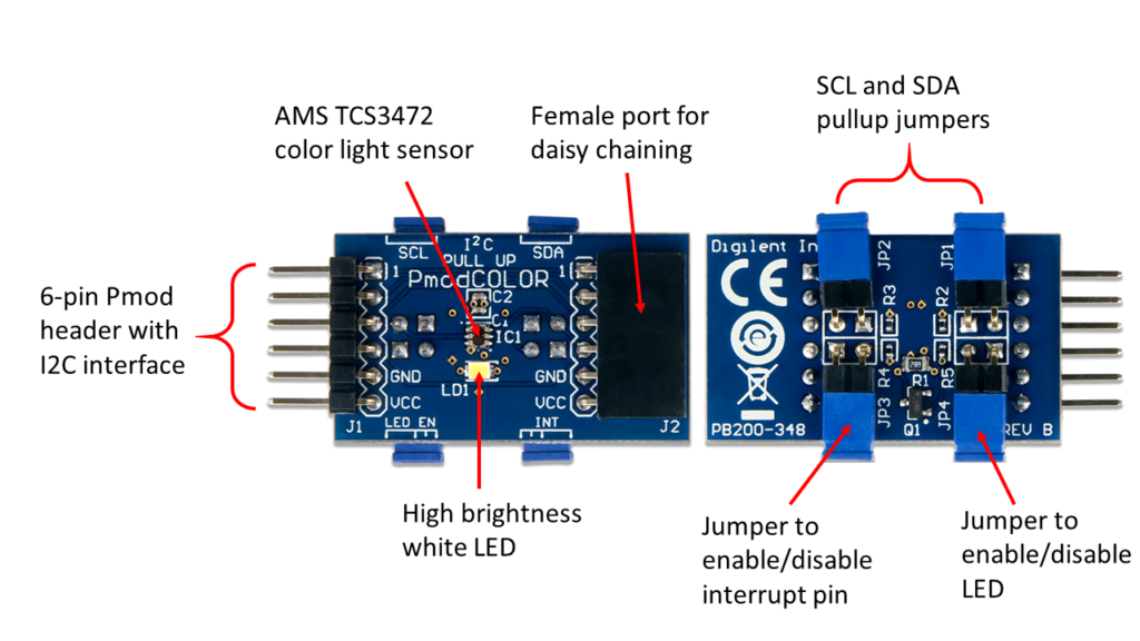
Sensors are the bridge to the physical world for electronics, each one with its own anthropomorphic qualities to give new life to your projects. This one, the Digilent Pmod COLOR, bestows the ability of color distinction. It is a color light to digital converter module that reports digital values for red, green, blue (RGB) and clear light over a simple I2C bus. It incorporates a white LED to improve color determination in low light conditions, as well as an additional female header for daisy chaining multiple I2C modules together over the same I2C bus. All I2C Pmods require pull up jumpers on the SCL and SDA lines. Usually they are straight headers off the top of the board, however the jumpers on the Pmod COLOR had to be moved to the bottom of the board in order to not interfere with the sensitive color measurements!
The onboard AMS TCS3472 color light sensor integrates an IR blocking filter to accurately determine the color of objects as well as sense ambient light. The Pmod COLOR is highly sensitive with a wide dynamic range, making it ideal for use under varying lighting conditions and through attenuating materials.
How does it work?
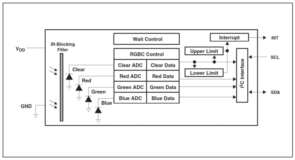
The onboard AMS TCS3472 color light sensor consists of an infrared filters, four photodiodes, four analog-to-digital converters (ADCs), data registers, an I2C bus and a state machine. Light first passes through the infrared filters that coat each photodiode, eliminating the IR spectral component of the incoming light and improving accuracy of the measurements. After passing through the IR filter, the light enters the photodiodes, one red-filtered, one green-filtered, one blue-filtered and one clear or non-filtered. The photodiodes produce leakage current based on the intensity of RGB and clear light present. The current from each photodiode passes through an ADC and gets converted to a 16-bit digital value that is stored in the data registers. Users can then access the digital RGB and clear light values over a simple I2C bus and program their host board to take certain action based on the RGB components and intensity present.
The Pmod COLOR also has an onboard white LED and four jumpers. The white LED is present to improve color measurements of objects and is very bright, therefor we recommend users do not stare directly at it. The jumpers are present to control the SCL and SDA pullups to VCC, enable/disable the active-low interrupt pin, and to enable/disable the white LED. More can be read about use of the jumpers in the Pmod COLOR reference manual.
Applications
Applications of the TCS3472 include RGB LED backlight control, light color temperature measurement, ambient light sensing for display backlight control (which we’re all familiar with as its used in cell phones and tablets), fluid and gas analysis, and product color verification and sorting which is frequently use for automation in the industrial space. If you’re interested at all in physics, be sure to check out the technical documents provided by AMS on interesting topics such as color temperature measurement and colorimetry. AMS has also provided white papers on sensitivity to wavelength and temperature, improving lux accuracy, color classification for sorting, and other topics using this sensor. The list and links are below:
- Imroving Color Sensor Lux Accuracy
- Calculating Color Temperature and Illuminance
- Color Classification with the TCS230
- Sensing color with the TCS230
- Colorimetry Tutorial
- Photo Sensor Response Part I: Sensitivity to Wavelength
- Photo Sensor Response Part II: Sensitivity to Temperature
- Compensating for Light Flicker on Optical Sensors
The Pmod COLOR is designed to work with any Digilent FPGA, Zynq or MCU board. It can be plugged into any host port on a Digilent FPGA or Zynq system board. With Digilent microcontroller boards, a little more care needs to be taken to figure out which Pmod host port supports the I2C protocol. Once identified however, the Pmod COLOR should be easy to get up and running with any Digilent MCU board. Just follow the Quick Start section of the reference manual to get started!
Getting Started
If you are an MCU user, we’ve written some libraries and example code to illustrate how to start getting digital color data. The example code was written in the Arduino IDE and should work smoothly with the Digilent core for Arduino. For download instructions, see our tutorial on how to get started with the Digilent core.
If using the Pmod COLOR with a Digilent FPGA board, see our wiki page titled Using Pmod IPs for instructions on how to use our drag and drop Pmod COLOR IP Core with MicroBlaze designs. We’ve also done an additional color classification demo using the IP core that identifies colors presented on a monitor and prints “red,” “green,” “blue,” etc. to your screen.
Questions or comments? Use the comment section below or visit the Digilent Forum!
Talesa: just happened upon the pmod color sensor introduction. Have bought a few pmods in the past – for use with my students’ 2 myRIO. Has there been any work, that you know of, in this tech ecosystem?? Has someone ported the I2C/SPI approach to LabVIEW for these students’ benefit? I just ordered 2 pmod color sensors to the kids to play with – looking forward to your response. thx
Hi,
how to decide the color based on the 16-bit digital value obtained from ADC. Is there any standard procedure for this?