
In a previous post, I described where to plug in your Pmod when using a Digilent FPGA board. In this post, I will extend the discussion to Digilent MCU boards.
First, a couple of quick definitions: the male connectors on Pmod boards themselves are referred to as “Pmod connectors,” while the female connectors on host boards are referred to as “Pmod host ports.” The diagram below explains the distinction, using our newest microcontroller board, the Basys MX3, as the example.

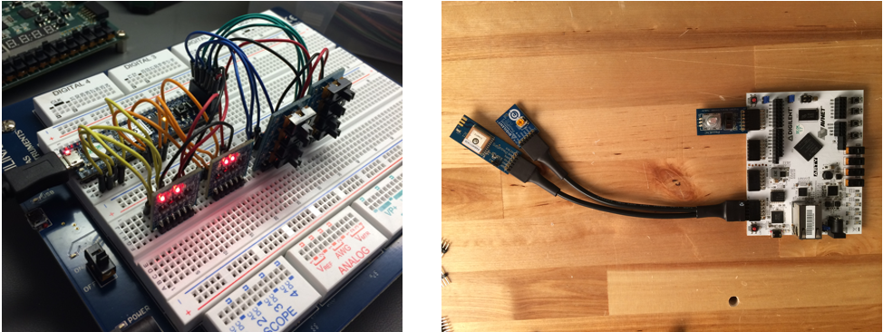
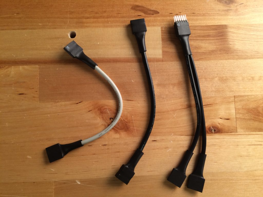
In general, there are three main ways to connect a Pmod to a host board, mechanically speaking. The first method is to plug the Pmod directly into a Pmod host port. The second is to use Pmod cables, which come in several varieties including 6-pin, 12-pin and 12-pin to dual 6-pin splitter cables. Lastly, Pmods can be wired up using MTE cables or individual jumper wires, which can be necessary if the host board does not have enough Pmod ports built in for your application. This last method is arguably the messiest but is still quite effective and a perfectly viable way to use your Pmod. In fact, we do it all the time!
In terms of signals, the majority of Pmods use one of four different serial protocols: SPI, I2C, UART or GPIO. When using FPGA boards, the communication protocol is less of a concern when deciding which host port or which pins to plug into as each pin on the FPGA can be assigned to be whatever you need it to be. When working with microcontrollers, a bit more care needs to be taken. With these general considerations in mind, let’s dive into the details.
I have a 6, 12 or 8-pin Pmod and want to use it with my Digilent microcontroller board.
There are two main categories to consider when plugging in your Pmod: electrical connection and mechanical connection. We will break the two down:
Electrical
The first thing you need to know is what communication protocol your Pmod uses. Pmods use SPI, I2C, UART or GPIO. There are a couple other categories, like H-bridge and I2S, but those can simply be included in GPIO for now.
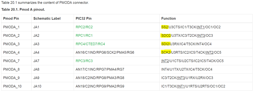
Once the communication protocol is known, you’ll need to identify which port(s) on your microcontroller board support that protocol. To do that, you may be able to check the silkscreen of the board to find out quickly, but that information is not always printed. A more sure way is to check the reference manual. For example, the image below shows the pinout for Pmod Port JA on the Basys MX3 MCU board. You can see in the function column, that the SPI signals are present on JA1-JA4. Therefore, a 6-pin SPI Pmod can be plugged into the top row of pins, while a 12-pin SPI Pmod makes use of additional GPIO pins and will take up all 12 pins available on the standard Pmod port.
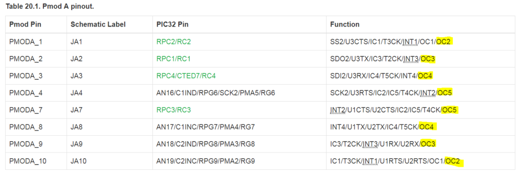
The same goes for I2C and UART. Look at the Pmod section of your host board’s reference manual and identify which host ports support the respective signals. All GPIO Pmods should work in any MCU board host port. The only thing to watch out for there is whether or not the Pmod requires PWM signals. If that is the case, you’ll have to make sure the pins align correctly. Just look for the output compare! See figure below.
Mechanical
In terms of mechanical connection, as mentioned previously, you can plug directly into any host port, or cable connections can be used. We have 6-pin, 12-pin and 12-pin to dual six-pin cables specifically for this purpose. If plugging two 6-pin Pmods into a single host port, you’ll want to use the 12-pin to dual 6-pin splitter cable, as exemplified in Fig. 2 above. Lastly, if you are trying to connect to a board without connecting directly to Pmod host ports (examples include using the shield headers on an Arty board, connecting 8-pin I2C Pmods, or connecting through a circuit on a breadboard), you can use MTE cables or jumper wires, also shown in Fig. 2. MTE cables can be purchased in packs of singles, 6-pin, 4-pin, 2-pin, or other styles.
So to sum up, if you’re using a Digilent MCU board, it’s really quite straightforward to decide where to plug in your Pmod. First, ask yourself what protocol it uses. Next, go to the host board reference manual and identify which ports support SPI, UART, I2C or PWM. They all support basic GPIO. Easy as that!
For any questions or comments, please use the comment section below or visit the add-on boards section of the Digilent Forum!