
I have never been shy in professing my love of Multisim. And MultisimLive. So it came as no surprise to me when I found out I could program my favorite FPGA boards by using pictures instead of words. Needless to say I was pretty excited. What do I mean? Let me explain.
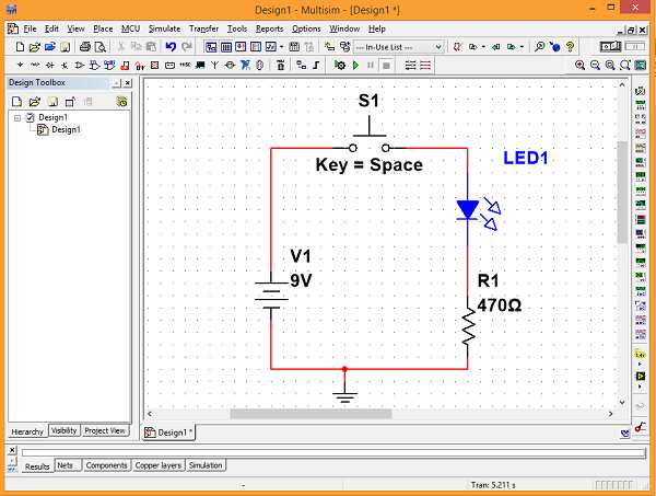
If you’re not familiar with Multisim, it’s a simulation software used to design and simulate analog circuits. Thousands of parts come preloaded to choose from, all with their own associated SPICE files so that the software can simulate the circuit without you having to actually build it. The beauty is that everything is done with images of the components without you having to write a single line of SPICE code.
But Multisim was, for many years, restricted to analog simulation only. That is no longer the case.
As long as you have a sound understanding of logic circuit design, you can design strictly logical circuits, test and simulate them, and then program your favorite Digilent FPGA trainer board with them.
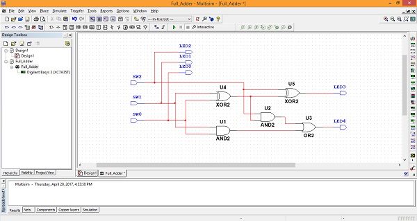
Multisim utilizes LabVIEW and Xilinx’s Vivado Suite to accomplish this. Be sure to check out my Instructable for a complete step-by-step tutorial on how to program your Digilent FPGA using Multisim.