
Welcome back to the Digilent Blog!
At some point, we have all noticed (whether we chose to admit it or not) that the world we live in is growing more and more digitized. While I am personally not opposed to this (I am writing for Digilent’s online blog after all), the need to produce analog voltage or current signals will always be present. Thankfully, when using a digital source, such as one of Digilent’s microcontrollers or FPGAs, there are a few ways to produce an analog voltage signal. One of the most fun ways (in my opinion) to do this is to use pulse-width modulation (PWM).
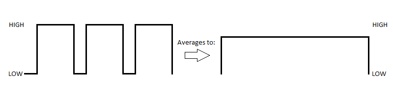
Pulse-width modulation (PWM) is a technique that takes advantage an electronic device’s capability to rapidly “pulse” one of its digital pins between logic high and logic low voltage states. The idea is that the switching between the two voltage states in a desired pattern will produce an “average” voltage somewhere between the high and low voltage inputs. If, within a given period, the pin is at a high voltage level more often than a low one, an overall higher voltage (but less than the full strength input voltage) will be observed.
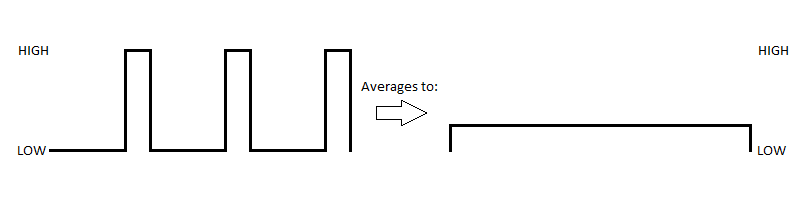
Conversely, if the pin is at a low voltage level more often, an overall lower voltage (but still greater than the low voltage input) will be observed.
The resulting average voltage can be achieved through the persistence of vision phenomenon, where our eyes cannot directly see the circuit switching between the high and low voltage states, or it can be accomplished through the use of an appropriate low-pass filter, which takes advantage of a capacitor to “smooth out” the pulses into a constant voltage. Because PWM is such an easy way to produce a desired average voltage from a digital source, it is commonly used to drive DC motors at different speeds or have LEDs fade in and out.
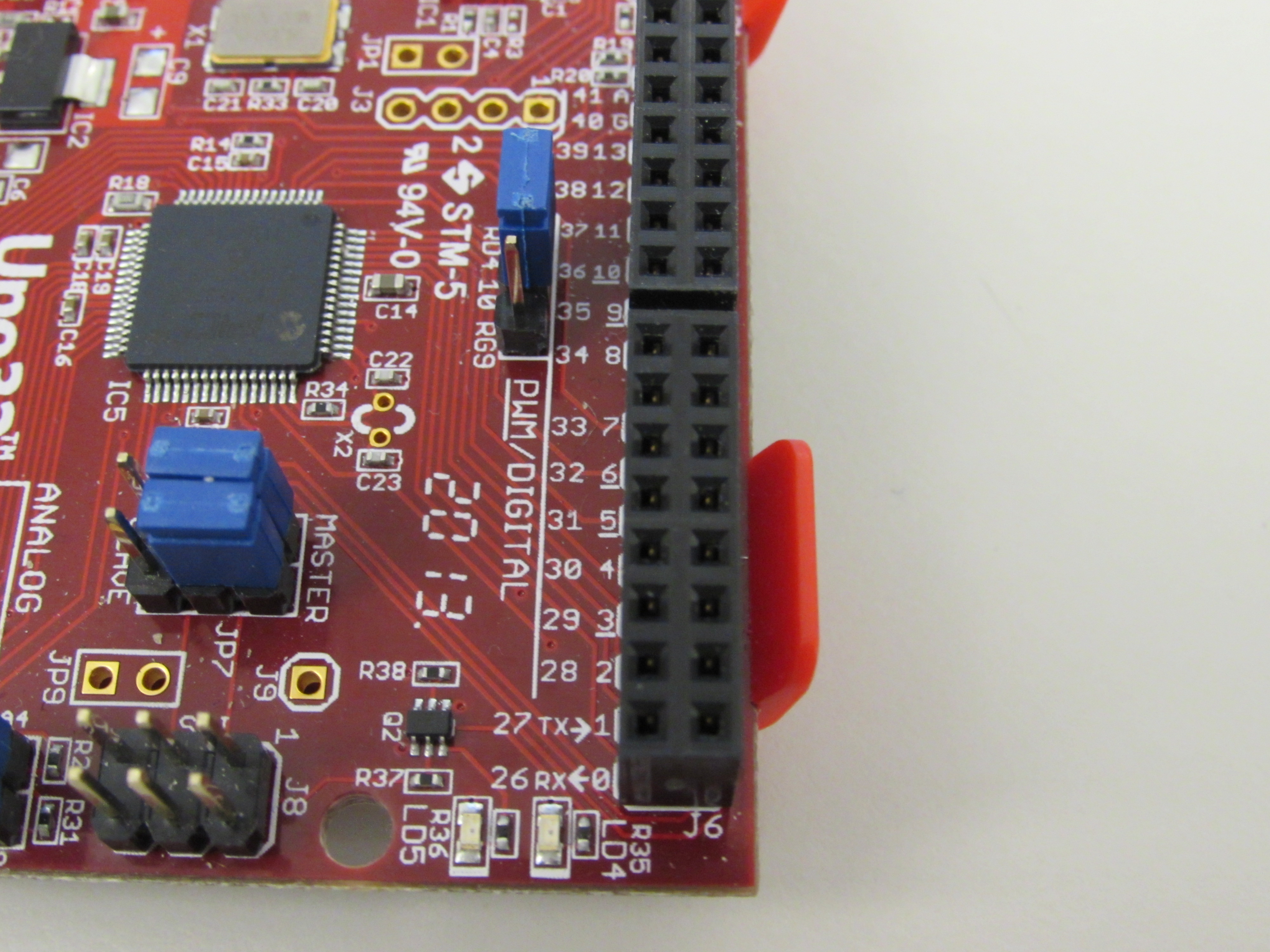
Digilent chipKIT boards, such as the Uno32 and the uC32, have several digital pins that are capable of performing pulse-width modulation, as indicated by the underline that appears beneath the numbers on the silk screen.
They are able to produce the PWM signal by issuing them an analogWrite() command inside MPIDE with a given value between 0 and 255. The analog write function is technically able to handle values up to 1023, but because the timers within the Uno32 and uC32 are only 8 bits long, this restricts the time frame that the ratio of high to low voltage can be measured in to 256 ticks. However, this still allows you to choose a voltage between 0 and 3.3V in approximately 0.013V increments, so for a lot of applications you do not usually need to be more precise than that. To learn more about how the hardware within microcontrollers works with pulse-width modulation, check out this Learn module!
One Comment on “Pulse-Width Modulation”