
I recently took an Analog Circuit Design course as one of my Electrical Engineering electives for my Bachelor’s degree, and the projects my lab partner and I worked on were definitely a step up from our basic transistor amplifier labs (which were already finicky for newbies). The last project was definitely the hardest: an AC voltmeter that displayed RMS voltage for sinusoids between 10Hz and 100kHz, a 50dB/decade roll off at the cutoff frequencies, 0.1dB ripple in the passband, and a 1% tolerance for the correct displayed value.

half-power point or -3dB point. Photo from here:
https://commons.wikimedia.org/wiki/File:Sine_wave_voltages.svg
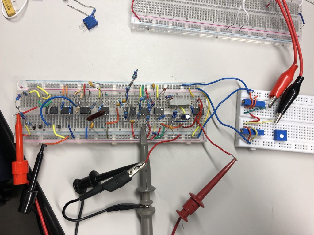
This project was based around the use of operational amplifiers, and our final design ended up with eight op amp ICs, a few being dual package op amps. This was due to various unexpected non-idealities that we were encountering when implementing dual package op amps, as well as the various problems that arise when building more complicated circuits on a breadboard. The biggest problems were noise from all the wires we had to use, and power coupling noise. We were using cables for the oscilloscope, function generator, and power supplies that were all a couple feet long, along with a breadboard with many connection wires and approximated resistors consisting of up to five resistors soldered together to meet the design schematics. All this added up to some really noisy signals when using the benchtop oscilloscope in the school lab.
Our lab equipment is generally good stuff from what I can tell and had served me well with less complicated circuits, however, the sensitivity was driving me insane and time was running out to get the project tested and demonstratable. I decided to try using my Analog Discovery 2 for the oscilloscope and power supplies just as a means of comparison. The incredible thing was that the noise was greatly reduced due to the much shorter and thinner cables on the Analog Discovery 2, versus the benchtop oscilloscope and power supplies. This allowed me to more accurately test our design and verify that specs were being met. It just goes to show that having some fancy, expensive benchtop tools is great and all, but sometimes that under $300 tool will surprise you with a more beneficial performance. I wish I had taken more pictures of what was actually going on to show you all, but in the heat of the moment I only got one shot from my workstation:
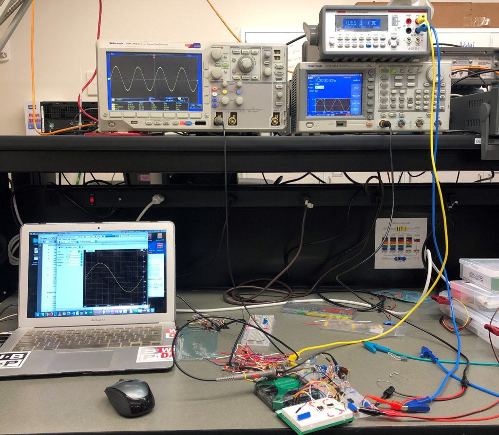
Photo taken by me.
Thank you Analog Discovery 2!