
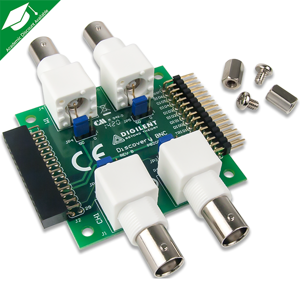
I was approached with the idea to prototype an “audio adapter” for the Analog Discovery 2 to display audio signals on the oscilloscope and being the audio nerd I am, I was all about it. I looked to the BNC Adapter for inspiration for the PCB design, since most of its aspects I could transfer directly to my audio adapter design. What I noticed was not only does it have BNC connectors for the Waveforms Scope, but it also has connectors for the Wavegen output. Cool, I thought.
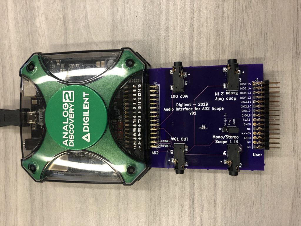
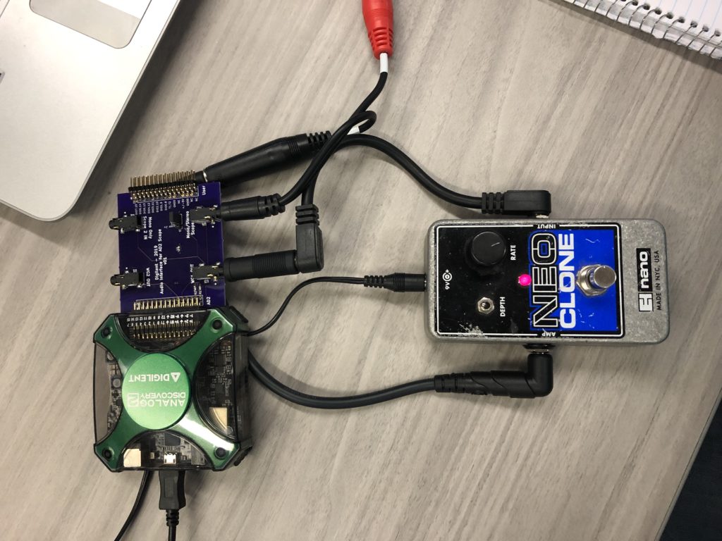
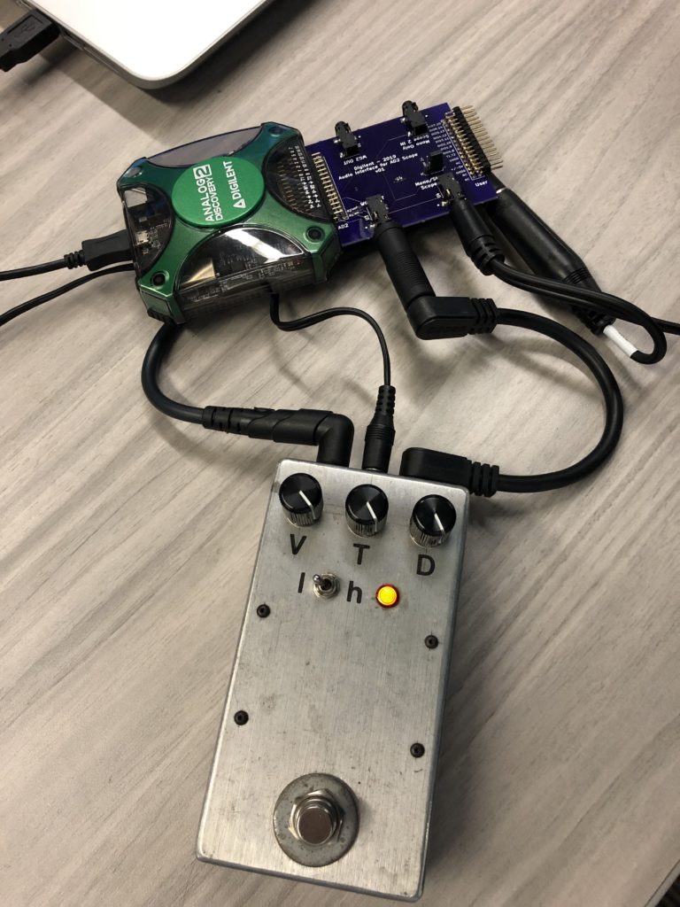
I figured the most universal audio jack to be a 3.5mm cable jack. Any other type of audio output should be adaptable to that. I thought about how the Wavegen instrument would be helpful in audio analysis for applications where a reference signal would be needed and decided that I would include those outputs with the 3.5mm jack as well. I thought about how fun it would be to put a sine wave through various guitar pedals just to see what would happen on the scope. So, after my board was fabricated and assembled, I did.
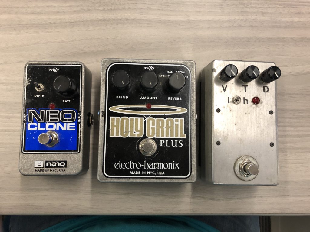
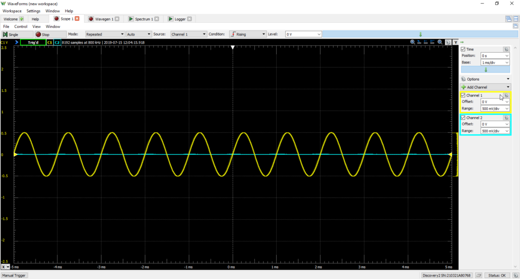
I wanted to try different types of effects rather than multiple examples of a single type so I grabbed distortion, chorus, and reverb effects pedals. I had only pieces of ideas of what to expect with these different effects so I tried all sorts of settings with all sorts of Waveforms tools until I found what settings maximized the visual effect on the scope but what other instruments provided interesting visual analysis results. Keep in mind, all of the analysis I did was visual and motivated by pure curiosity. I used a sine wave at 1kHz and 500mV to simulate a frequency in the range of an electric guitar and an approximated maximum output voltage for all tests. I have included screenshots from Waveforms where it made sense but I also made short videos from Waveforms and included those after all the screenshots for each pedal. Some things are better described with video (like the reverb effect.)
Using an Electro-Harmonix Neo Chorus with the “depth” switch in the upright position (largest amplitude of modulation), turning the “rate” knob to about the 3 o’clock position, then zooming out the time step on the Scope channel I was able to observe (although subtle) an envelope being applied to the input sine wave!
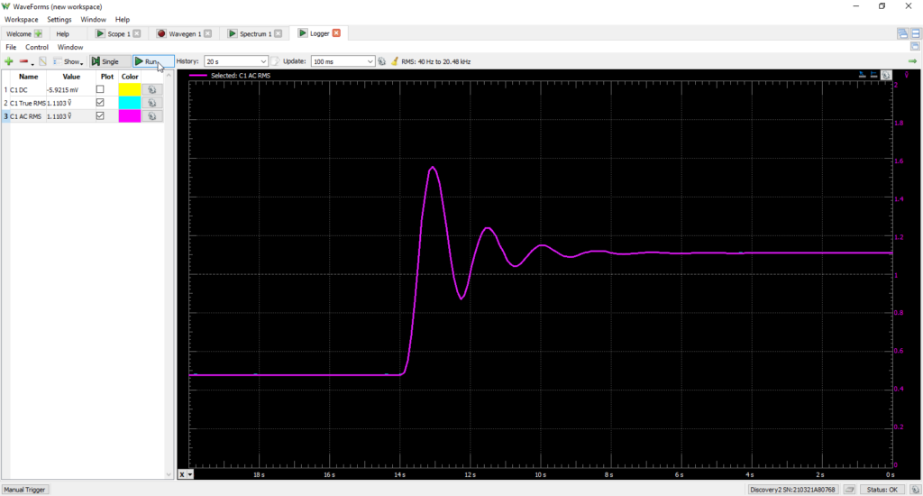
I wanted to see if I could visualize it more with another tool so I opened up the Logger and recorded the DC value of that channel. Since the modulation was causing a dynamic DC offset, the DC plot had a periodic-type behavior that increased in frequency as I turned the “rate” knob to a higher modulation rate! It truly is modulating! This should help those students studying Continuous-Time Linear Systems listen to their math a little differently.
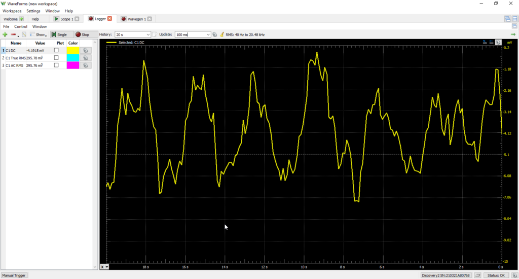
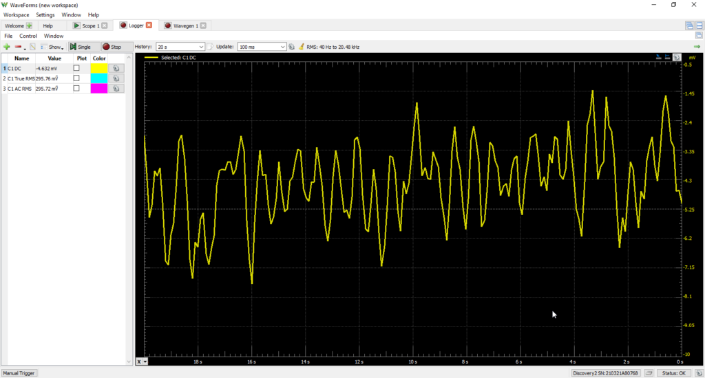
The DC voltage of the Neo Clone with “rate” at highest.
Approximates a more frequent AC signal.
Notice in the Scope view that the whole thing is alternating slightly.
The Data Logger view attempts to isolate this periodicity.
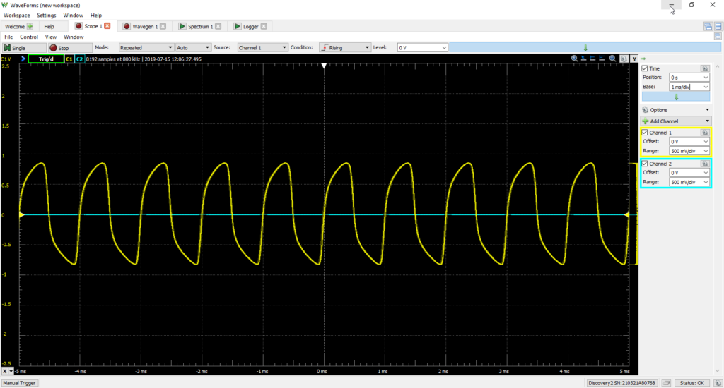
Next up was a distortion pedal that my friend Darren Chase built for me as a trade for a heap of graphic novels from the 1960s-70s. It is a clone of a Fulltone OCD overdrive as per my request at the time. Just turning the pedal on turned the sine wave into a triangle wave, even with all parameters dialed down. Then, turning the “tone” knob up introduced asymmetry to the triangle wave and turning the “distortion” knob up caused a “shark fin-like” edge to appear at the leading edges of each half-cycle.

Notice the introduced asymmetry.

This is high distortion.
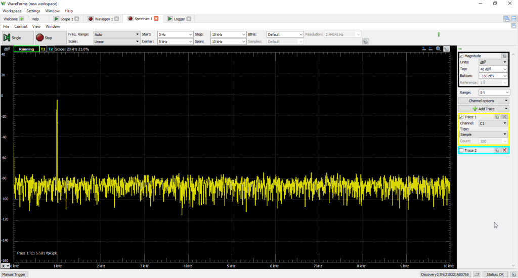
I popped open the Spectrum tool to look at the distortion in the frequency domain. I noticed that turning the pedal one introduced even and odd harmonics with odd harmonics being dominant. Turning up the “tone” knob seemed to increase the magnitude of all harmonics equally while turning up the “distortion” knob seemed to increase the magnitude of only the even harmonics. Interesting, I thought.

This is the triangle wave in time domain.

Seemed like all harmonics increased in magnitude.
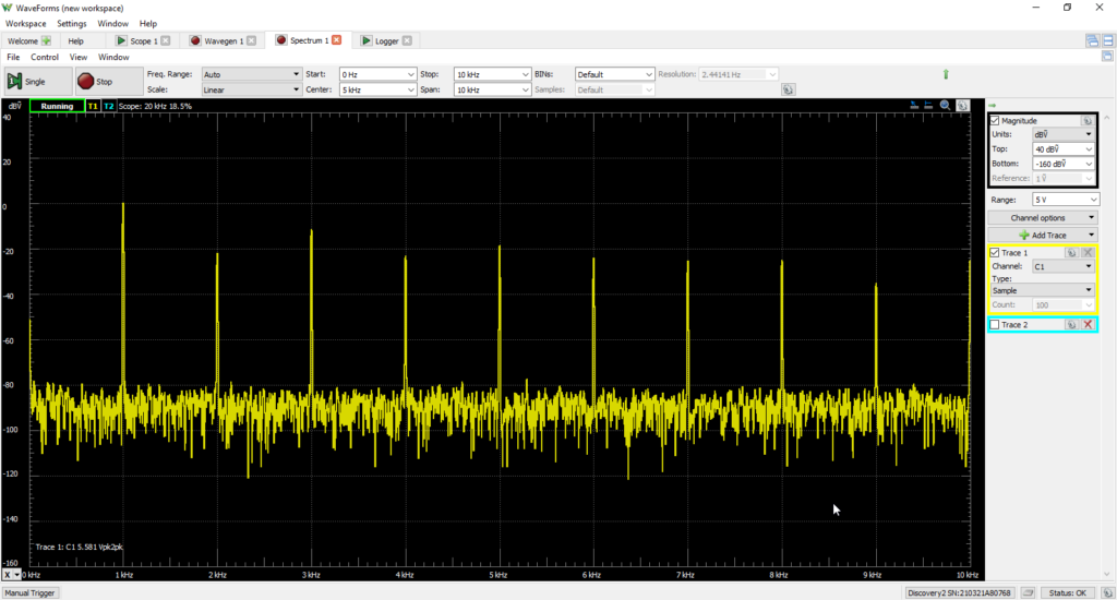
Seemed like only the even harmonics increased in magnitude.
Finally, I really wanted to see what I could generate with a reverb pedal, if anything. I used an Electro-Harmonix Holy Grail Plus. After messing with the different types of reverb and the other knobs for a bit, I was able to exaggerate a peculiar effect that I noticed and did not expect at all. On the “Hall” setting, the pedal is trying to emulate the echo characteristics of a large concert hall or something similar.
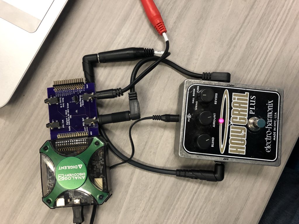
Using this setting, I started with the “blend” (weighted sum of input signal and processed signal) and the “amount” (magnitude of processed signal in the mix and decay time) all the way down, then turned the “blend” all the way up followed by turning the “amount” knob all the way up, I noticed that the amplitude of the sine wave would not only grow but the peaks would express a sort of “dampened modulation”. Trippy, I thought. Note that I turned up both knobs rather quickly but then left them all the way up without adjusting them anymore. The “damped modulation” is happening after both knobs have been turned all the way up quickly then left alone.
I remembered the Logger instrument and how it helped me with the chorus pedal, so I did the same experiment using the Logger and captured a very pretty ringing behavior! I would have never guessed I was going to see something like that using a reverb pedal, although typical use of a reverb pedal does not involve such drastic dynamics with those parameters.
I’m curious what other types and examples of these types of guitar effects pedals can do when put into an oscilloscope, spectrum analyzer, or data logger. Nothing like taking the fun to the next level and learning a thing or two about it under a different light. If you are curious about scoping some sound effect or audio signal in Waveforms, using an Analog Discovery 2, or questions about my “Audio Adapter”, please leave a comment! Thanks!
That looks awesome! Would you be willing to share the schematic for your audio adapter? Is love to build one for myself.
Hello, could you maybe show me how the sound waves look like using effects such as delay, reverb, wah, distortion in contrast to the normal sound wave? Thanks alot
I have perhaps a naive question. What is the difference between capturing guitar/pedal waveforms using a USB interface (like a FocusRite) into DAW software and using an analog pathway to a traditional electronic oscilloscope?
If the interface and USB-DAW both comply with Nyquist sampling at about 44 kHz, would the wave forms look very similar? Have you compared these two approaches (digital sampling and pure analog) using Fourier analysis?
What key point am I missing on the advantage of the pure Analog pathway?
Thanks
Jerry