
While WaveForms 2015 is an incredibly multi-purpose and useful tool for working with electronics, it can be a little intimidating to account for and understand all its capabilities. Today we are going to go over one of those many features (The Impedance Analyzer) so that you can get the most out of this powerful software.
So when would one use this?
If you are working on a high speed application or with specific frequency requirements, you might need to account for something known as parasitics. If you are unfamiliar with this term, a definition is included below (from the Digilent wiki).
The total counteractive force to the flow of electrons through a system is known as impedance. This can be abstractly thought of as the resistance of the circuit and can be measured with an impedance analyzer. But if impedance is just a way of representing the resistance a circuit offers, why is a fancy tool required to do so and not just a digital multimeter? The reality is that no real components, resistors, capacitors, or inductors, are purely resistive or reactive. Every component in existence is a combination of R, C, and L aspects; the unwanted aspects are called parasitics.
The Impedance Analyzer can provide information pertaining to impedance, admittance, inductance, capacitance, phase, and quality factor of the system. It is available in the WaveForms 2015 software (version 3.6.8 or newer) for the original Analog Discovery, the Analog Discovery 2, and the Electronics Explorer board, and a detailed description of how to go navigate the workspace and measure a simple low pass filter is included on the wiki page.
To start this tutorial, you will first need to gather your materials. This includes:
-
WaveForms 2015 software (version 3.6.8 or newer is required)
-
A computer with a USB port
-
A load of interest to test and a resistor of a known value
Next you will open the Impedance Analyzer in WaveForms 2015 and select your instrumentation tool as well as the Impedance tool.
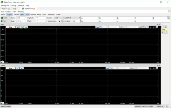
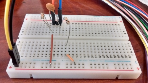
Once you have adjusted the relevant settings it is time to set up the circuit.
The Impedance Analyzer accepts two different arrangements for the load of interest and the reference resistor, and to get a clean impedance measurement, different reference resistors are recommended based on the capacitance and inductance of the load.
The tutorial then goes on to show the results of analyzing the circuit from 20 Hz to 25 MHz with a 10 kΩ with a 100 samples per frequency point.
Hopefully this overview is enough to get you familiar with and started with this useful tool. If you have any additional question please head over to the Scopes and Instruments section of the Digilent Forum.