
Digilent’s New Analog Discovery Pro ‘Opens’ It Up
As design requirements become increasingly more complex, engineers around the world are asked to shorten design cycle time and increase output. Flexible test equipment that can research, validate, and test is one of the ways engineers can speed up this process. This need in conjunction with the rapid adaptation of the workface due to Covid-19 is putting pressure on test and measurement companies to provide flexible and portable solutions at the same time as the semi-conductor industry is facing factory shutdowns. Answering the call in the coming months is the ADP3450, the first in the line of Analog Discovery Pro products, which in addition to providing a reliable instrument when connected to WaveForms, also introduces an entirely new way to interact with a portable device of its kind, Linux Mode.
Linux Mode provides an on-device operating system that, when combined with WaveForms SDK, is a flexible jumping off point for all kinds of custom tests and applications. As a classic demonstration of each operation Mode of the device, I have two Test and Measurement takes on the classic LED blink example: an automated test of an ADC, and a very simple power measurement demonstration.
Testing an Analog to Digital Converter
The first demonstration is an automated test of an analog to digital converter, which I have chosen in the form factor of a Pmod for simplicity’s sake. Automation of the test is accomplished using WaveForms SDK to control the AWG to stimulate the module with analog signals and control the oscilloscope to capture and decode the SPI transactions.
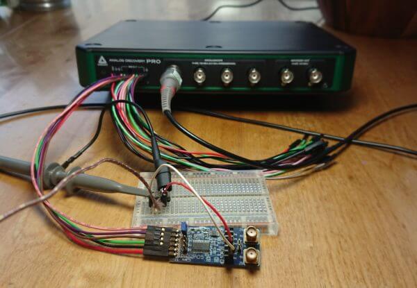
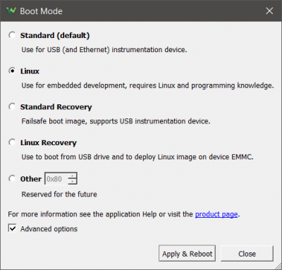
The ADP3450 defaults into Standard Mode, which allows you to connect via USB or ethernet to a computer running WaveForms to take quick measurements as you would on any standard USB Oscilloscope or Logic Analyzer. Booting into Linux Mode is as simple as changing the boot Mode setting and clicking apply:
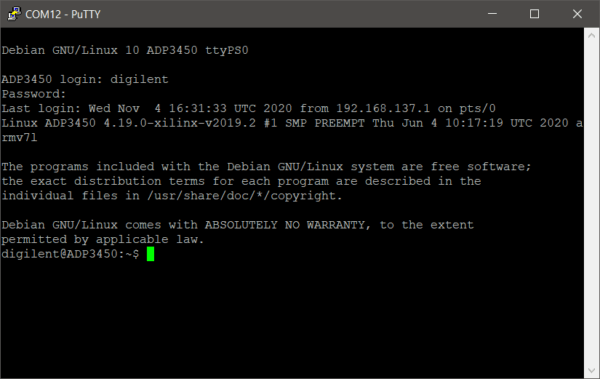
Once booted, a terminal application can be used to connect to the serial port of the device. For this example, Python is used to write the test, although several other languages can be used as well to write the script.
This script in its entirety configures the PmodAD5 via SPI and iterates over a list of voltages used to set a DC signal from the AWG. It then issues a read command over SPI, records the results, and continues to the next voltage until there are none left. The results are displayed on the terminal once the test is completed.
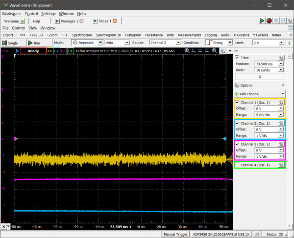
Once properly mounted the script can be run, and the output is as seen below:
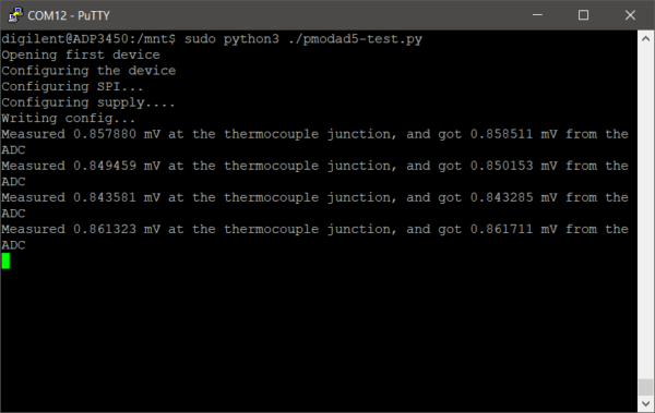
In a real system, the oscilloscope could read the actual analog data, compare the results and issue a pass or fail based on set criteria.
If interested in the development of the script and WaveForms SDK functions there is a full write up on the details of this automated test.
It is of note, that the Linux Mode and Standard Mode are independent, and each have their own recovery method. This way, if you get a little too creative in Linux Mode and something goes wrong, Standard Mode continues to operate as expected, and you can use the Linux recovery Mode to reflash that portion of the device at your earliest convenience.
The next demonstration uses the traditional USB Instrument Mode, Standard Mode. To switch Modes, simply select the boot Mode and reboot.
A common measurement in the design process is power, but inherently most oscilloscopes measure voltage. With some basic math functions power measurements can be calculated in real time. To demonstrate this, a basic RC circuit will be used.
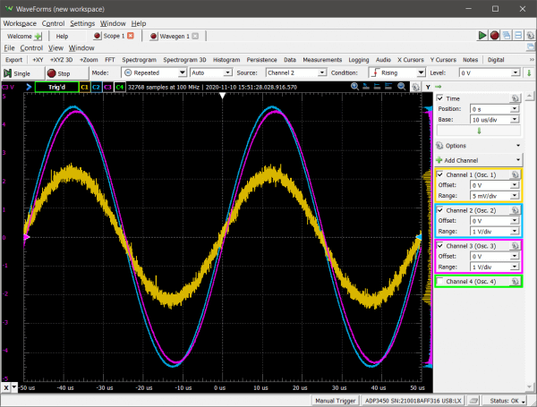
For this test we enabled three of the four available oscilloscope channels in WaveForms:
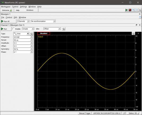
Then used the AWG to stimulate our basic circuit:
Back in the Oscilloscope, the voltage drop across the sensing resistor (Ch 1), the voltage drop across the entire circuit (Ch 2), and the voltage drop across the two resistors (Ch 3), can be seen.
Math channels can be added for each channel to calculate power for each component using the various node voltages captured by the oscilloscope and the known resistor values. First adding a math channel for the power across resistor one:
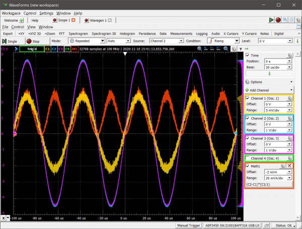
Then for the following resistor and capacitor. For clarity’s sake the oscilloscope channels have been hidden:
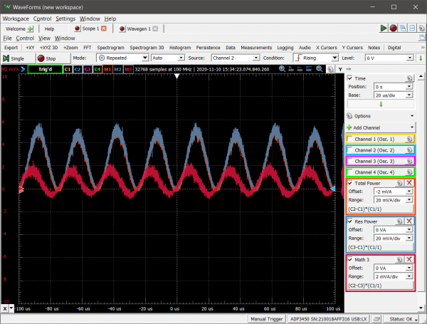
For each math channel, the average of each power measurement can provide more clarity:
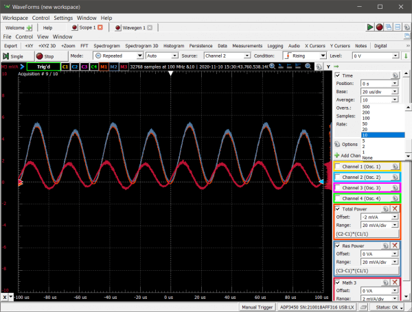
Since these measurements and calculations are taken live with an oscilloscope further exploration can be achieved by adjusting the stimulus of the circuit.
For more details, there is a full write up of this example as well.
This example focused primarily on the Oscilloscope and Waveform generator instruments, but a multitude of calculated tests can be accomplished using the 12 instruments on the device. Including frequency domain calculations with the spectrum analyzer and bode plot in the network analyzer, impedance analysis, and stimulus, capture and decoding of digital signals in the digital instruments. Outside of the existence of these instruments the ADP3450 offers much more that should be mentioned.
The full set of specifications can be found here.
As a summary of the capabilities, measurements taken on the device itself or via WaveForms can take advantage of faster data streaming via ethernet, on-device storage to capture buffers of millions of samples, 14-bits of resolution and integrated BNC connectors, and to drastically increase the capturable signals, different sample Modes can be used to capture repeated signals up to 0.5GS/s.
I have one question that what is swap space in linux?
Linux swap space is a dedicated area on disc used to temporarily store content from RAM memory when the content is not being used. It can be thought of as “virtual RAM.” This makes it possible for a programs to use more memory than is actually in the machine by swapping the content between RAM and disc.
Using the ADP3450 I just purchased, I cannot get the linux program to boot up sufficiently to run the linux image replacement functionality. The equipment is essentially non-functional in both linux and waveforms interface functionality due to the inability of the linux program to finish the boot process. Could you publish an alternate method of downloading the linux image to a non-functioning hardware. I saw in the support center that such a procedure exists using JTAG interface, which I assume requires that the internal boards be opened up and a physical JTAG connection be made to them. I fear I might have much more difficulty with reinstalling the linux image, so a simpler always successful method would be required.