
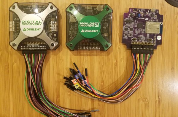
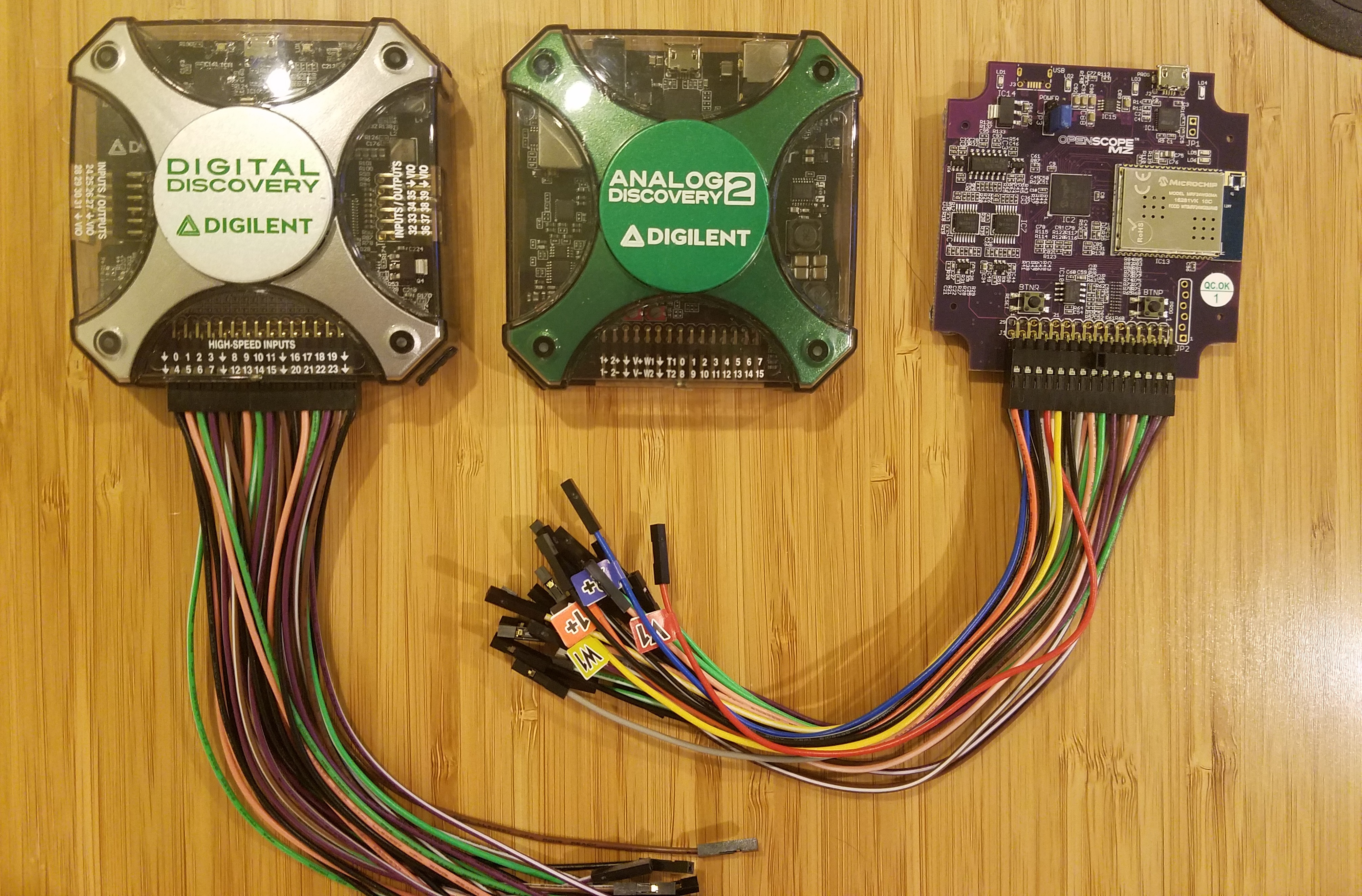
Given that space is a premium on the surface of our Instrumentation devices, we opted to use a recessed male header and flywires as the default connection method. These flywires provide individual female terminated wires or MTE (Measurement and Test Equipment) cables for connection to circuits under test.
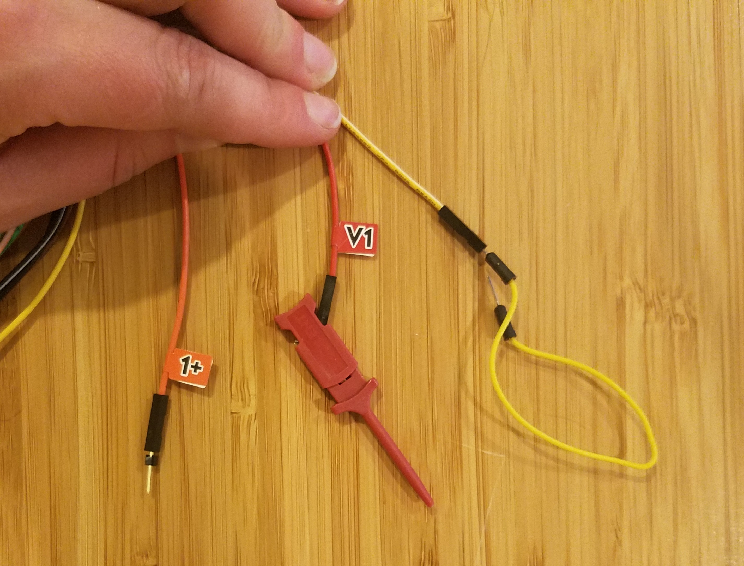
Since a female terminated wire is not always the most convenient option, there are a variety of ways to transform them. In the case a breadboard or Pmod Header is being used where a male connector is needed, the 6 pin gender changers can be broken into pieces and used to change the female wires into male wires. In the case that small pins need to be securely connected to the Mini-Grabbers, attach to the female wires in order to grab onto small components or surface mount or through-hole connected signals. A breadboard wire can also be used to transform the female connector into a male connector.
Since the Digital Discovery, Analog Discovery 2, and OpenScope are so versatile we’ve also made available several adapters that will either change the connection method, or in some cases influence specifications. We’ve also seen a number of custom adapters made by customers for their specific testing needs.
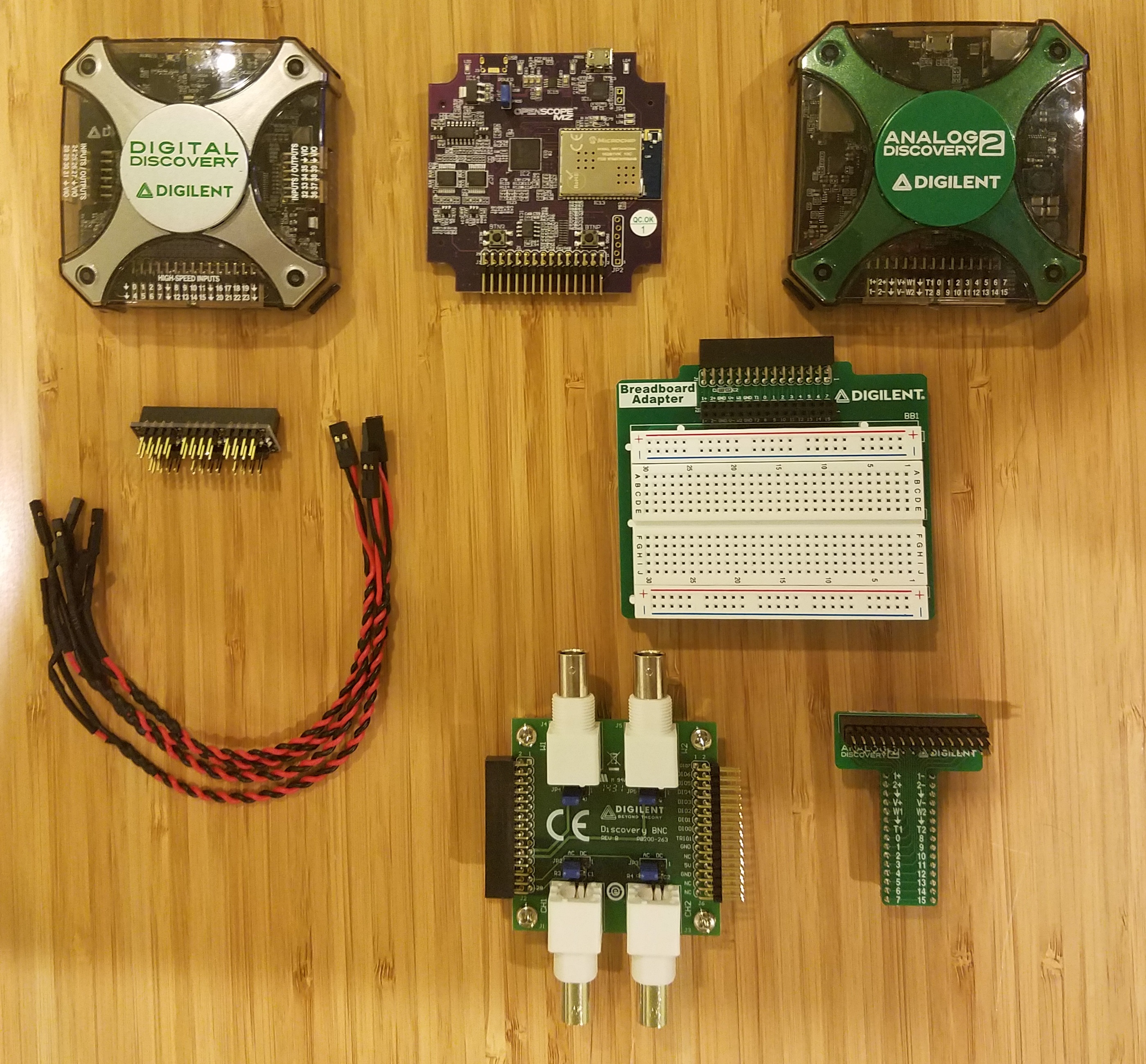
First, let’s talk about the Analog Discovery 2. The first adapter is focused on providing a secure connection and prototyping surface for the Analog Discovery 2. When used without it’s included breadboard, the Breadboard Adapter provides a small solderable prototyping surface and solderable power rails. This is also a great place to start when prototyping a custom adapter. A breadboard wire can be used to connect signals from the female 30 pin header to the prototyping surface. In the event that a solderless surface is more desirable, the Breadboard Adapter comes with a Half-Sized Breadboard that can be attached to the adapter. This adapter can also be used with the OpenScope. However, pay close attention to the OpenScope’s pinout as it is not the same as the Analog Discovery 2!

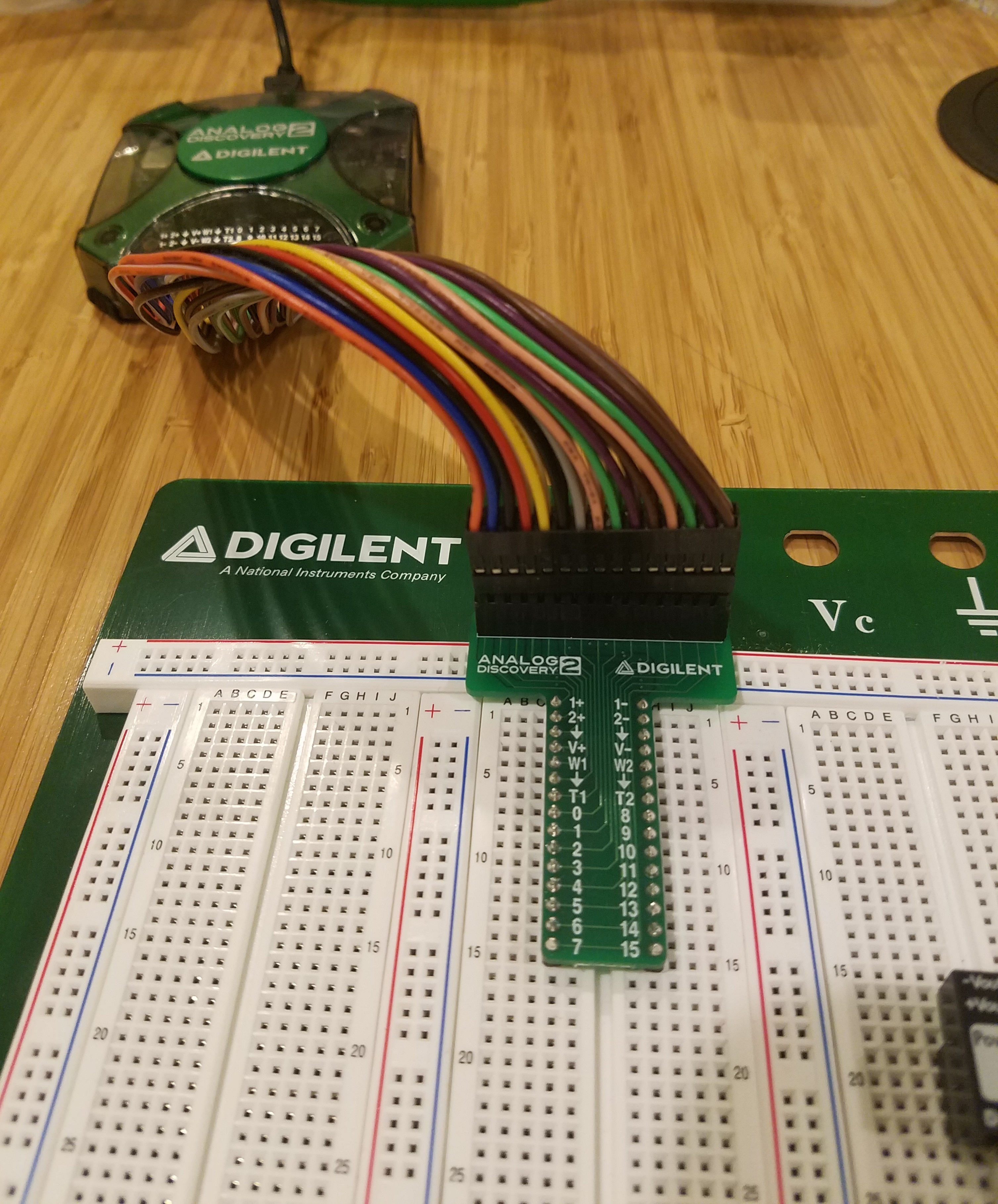
The next adapter was created specifically based on customer request. The Breadboard Adapter is great for small circuits where a Half-Size Breadboard is an appropriate size. However, often a larger breadboard is necessary for more complicated circuits. The Breadboard Breakout takes each of the signals on the Analog Discovery 2 and breaks them out into a Cmod like pinout, that can be securely attached to a breadboard. Like the Breadboard Adapter, the Breadboard Breakout can be used with the OpenScope, but once again make sure you pay special attention to the pinout of the OpenScope, as it is not the same as the Analog Discovery 2.
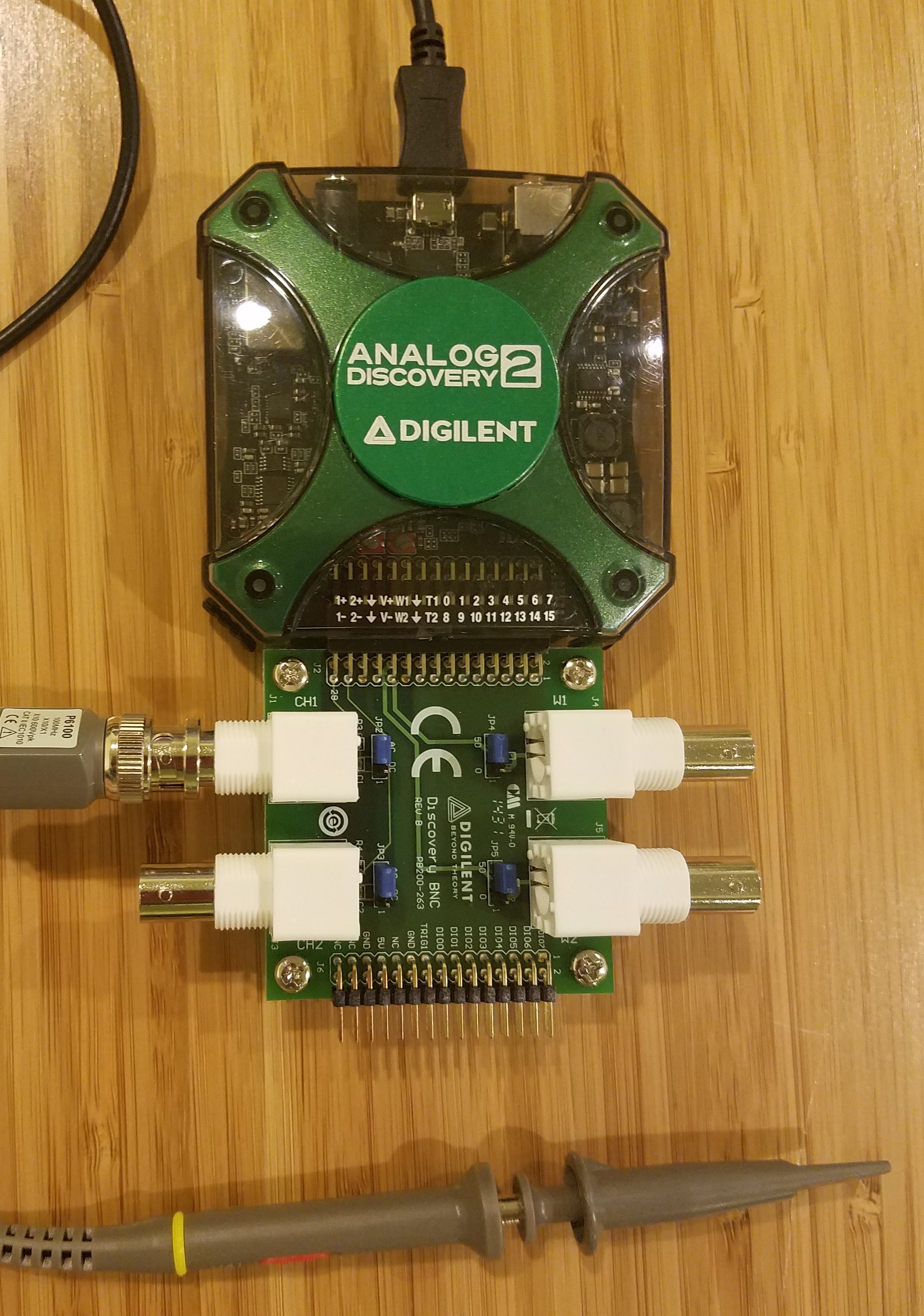
The last Analog Discovery 2 adapter provides not only an alternative connection method but also changes the specifications. The BNC Adapter provides traditional BNC connections for the 2 Oscilloscope Channels and 2 Waveform Generator channels. This allows traditional BNC Oscilloscope probes to be used with the Oscilloscope channels and BNC Probes to be used with the Waveform Generator channels. Changing the analog channels from the flywires to BNC connections increases the bandwidth of the Oscilloscope from 9MHz to 30MHz and the waveform generator from 9MHz to 12MHz! This is a significant increase in performance. In the event that the other 26 channels, trigger, grounds, power supplies, or digital I/O need to be used, these signals are passed through the connector where they can be accessed from the male header at the bottom of the adapter. The BNC Adapter can also be used with the OpenScope, but the pinout again is not the same.
For more information about how the Analog Discovery 2 adapters can be used with the OpenScope, check out this post on the topic.
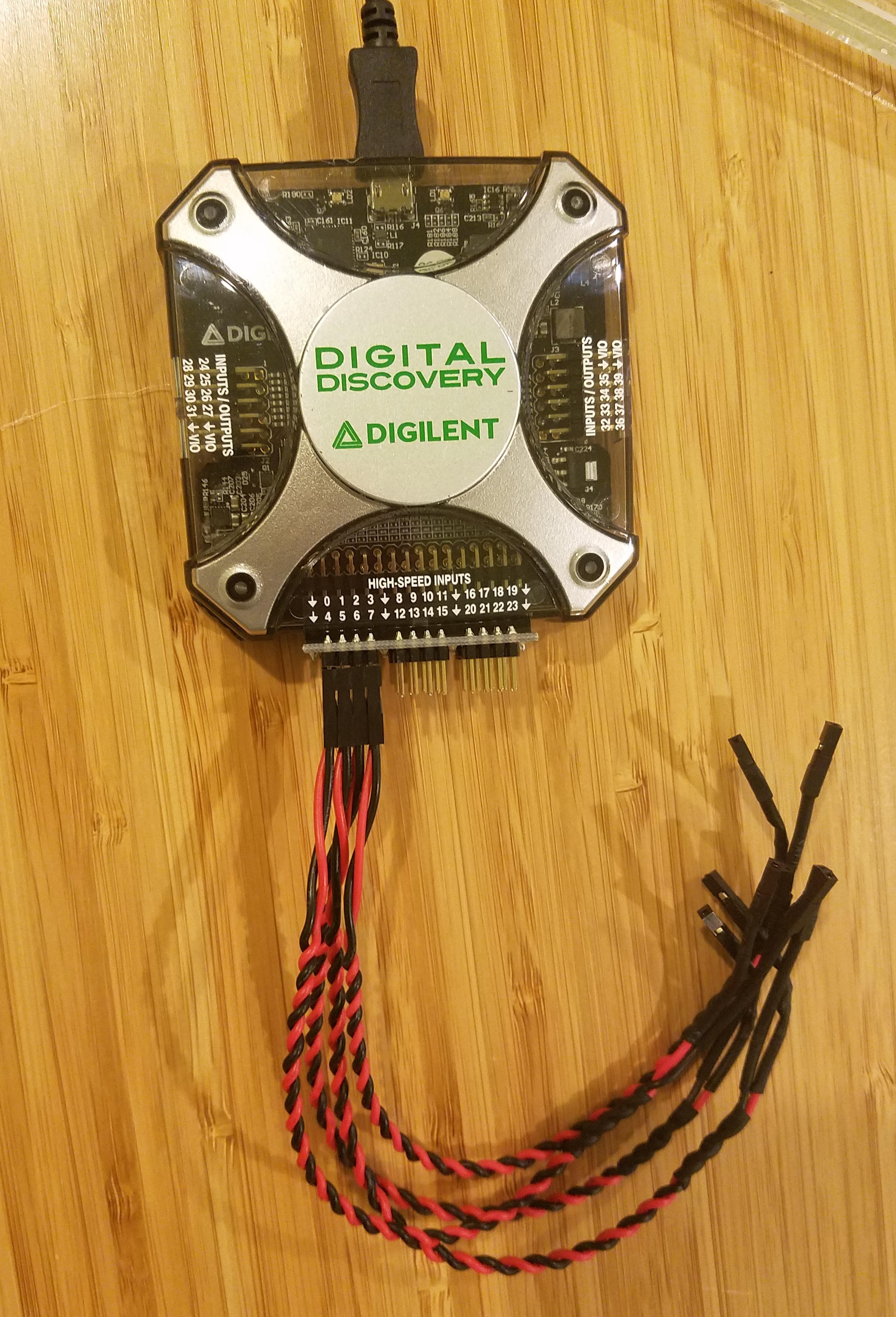
The last adapter is for the Digital Discovery. The Digital Discovery has 3 connectors, 2 on each side that each contains 8 Digital I.O, 2 ground connections, and 2 reference voltage supplies. The connector on the front contains the 24 high-speed inputs and 8 ground connections. This is the connector that the High-Speed Adapter is designed for. The High-Speed adapter maps each input pin to a ground pin, so that resistor terminated twisted probes called High-Speed Logic Probes, can be used. The High-Speed Adapter, when used in conjunction with these probes, is designed to reduce noise, allowing for sample rates up to 800MS/s!
If you’ve made your own custom adapter, or have ideas for adapters that you would find useful comment below!
For more information on any of these adapters or the test and measurement devices they are designed for, check out the Instrumentation page.
I’ve been thinking of designing a board specifically for impedance measurement, with built-in precision resistors, but I’m undecided about what connectors to use (different for measuring components and measuring cables, for example).