
Welcome back to the Digilent blog!
So you’ve heard about FPGAs and learned that you need to download Vivado, so you found a great guide on how to install Vivado, booted it up, got the extra files that you need, and … now what? If this sounds more familiar than you would like to admit, then you’ve come to the right place. We’re going to walk though a series of posts over the next few days to help you get up and running with a new Vivado project including: getting any extra files you need ready to go (available here), initially setting up a Verilog project in Vivado (the post you’re reading right now!), making changes to our Verilog project and XDC file to have it work on our FPGA, and finally generating the bitstream that we will use to program our FPGA. Let’s get started!
While it would be nice to think that we can simply just write up an FPGA program and configure our board with it and move on to the next program, FPGAs are complex enough that it is a good idea to add in some pre-made board files to help smooth out the programming process. I will be using Digilent’s Arty throughout the duration of this tutorial series and Verilog as my FPGA programming language of choice, as well as the 2016.4 WebPACK edition of Xilinx’s Vivado Design Suite.
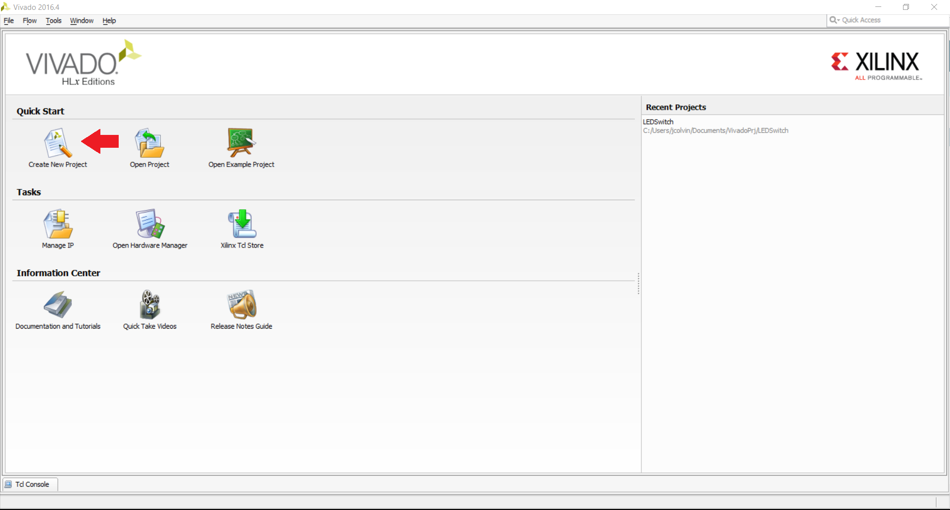
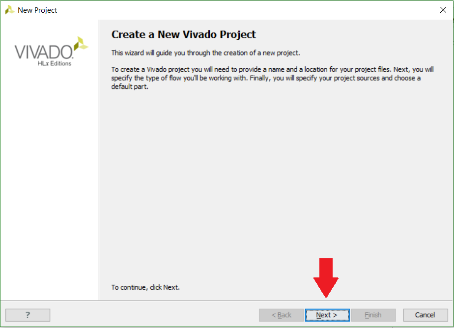
Let’s go ahead and create ourselves a new Vivado project. To do so, open up the Vivado application and click on the “Create New Project” button located in the upper left hand corner and then click “Next” on the next screen that appears to confirm that we do want to create a new project.
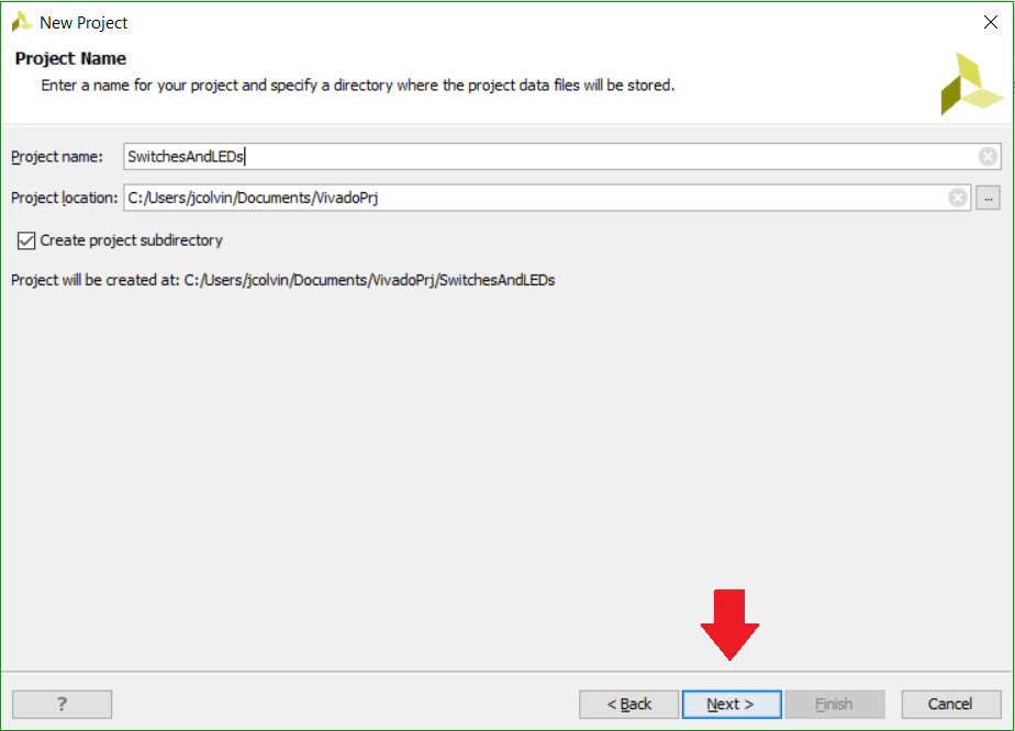
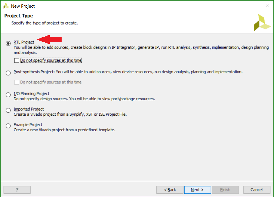
We’ll then be able to name our project and choose where we would like Vivado to save and generally store our project on our computer. The big caveat here is that both the name of our Vivado project, as well as the file path that our Vivado project is stored in must not have any spaces in it, otherwise you will run into some issues when Vivado is trying to create a project. Once you have chosen your name and file location, click “Next”, and on the next choose to create an RTL project (the first option) leaving the box to “Do not spot specify sources at this time” unchecked.
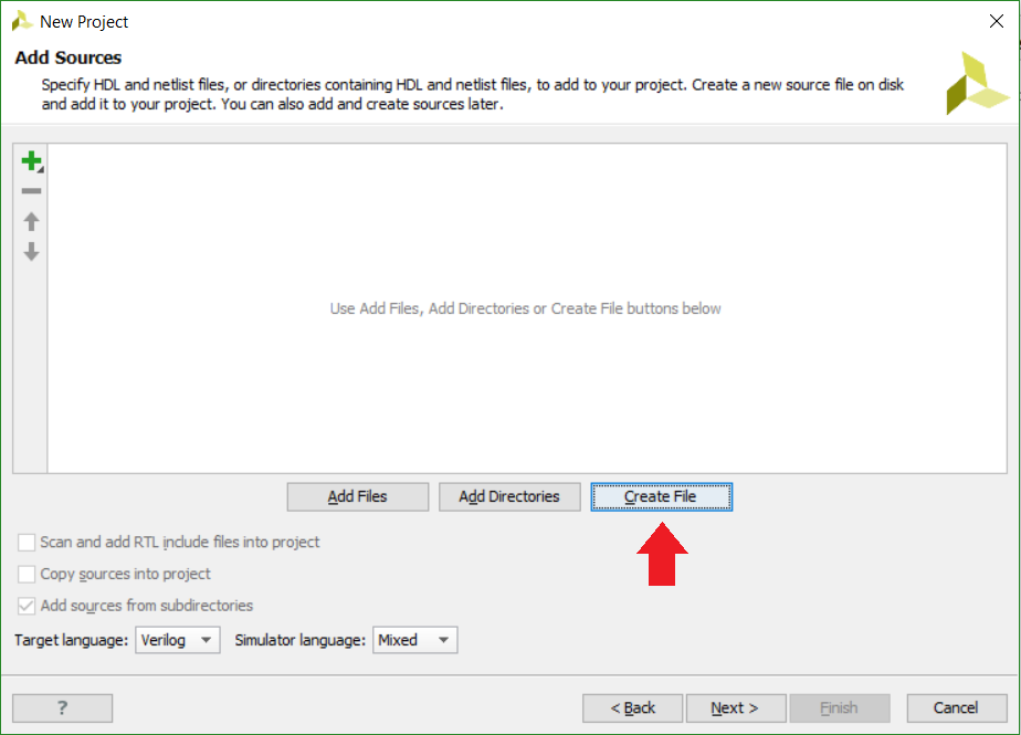
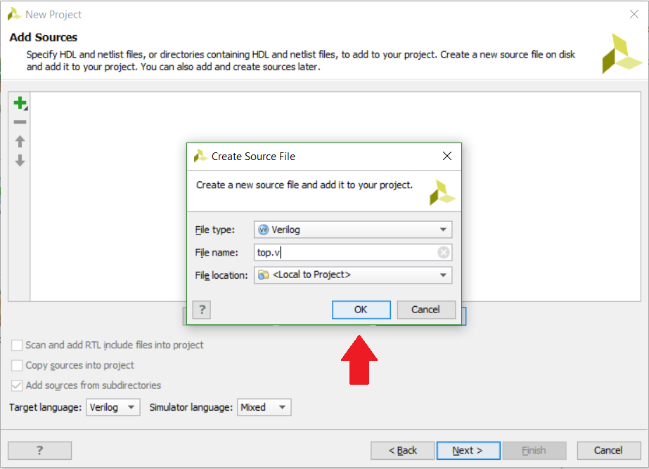
On the next page, choose “Create File” so we can create our own source file now rather than having to manually create it later. A “Create Source File” window will pop up where we can choose our file type of Verilog (for this tutorial) and the name of our Verilog source file. A typical name for these source files that will be the primary file that runs our program is “top.v” to signify that it is the file that runs (and calls) everything involved with that file. Once you’re done with that, click “OK” and then click “Next”.
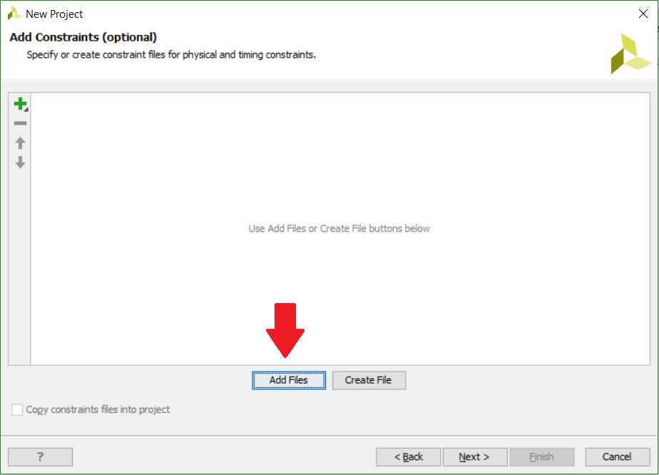
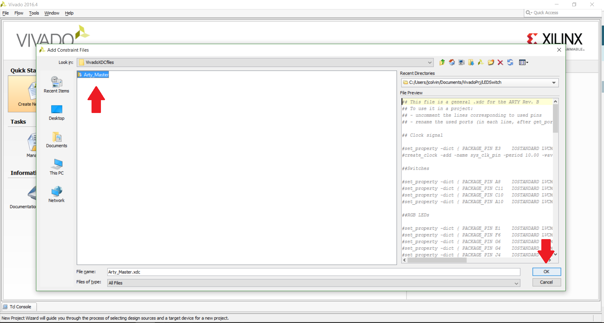
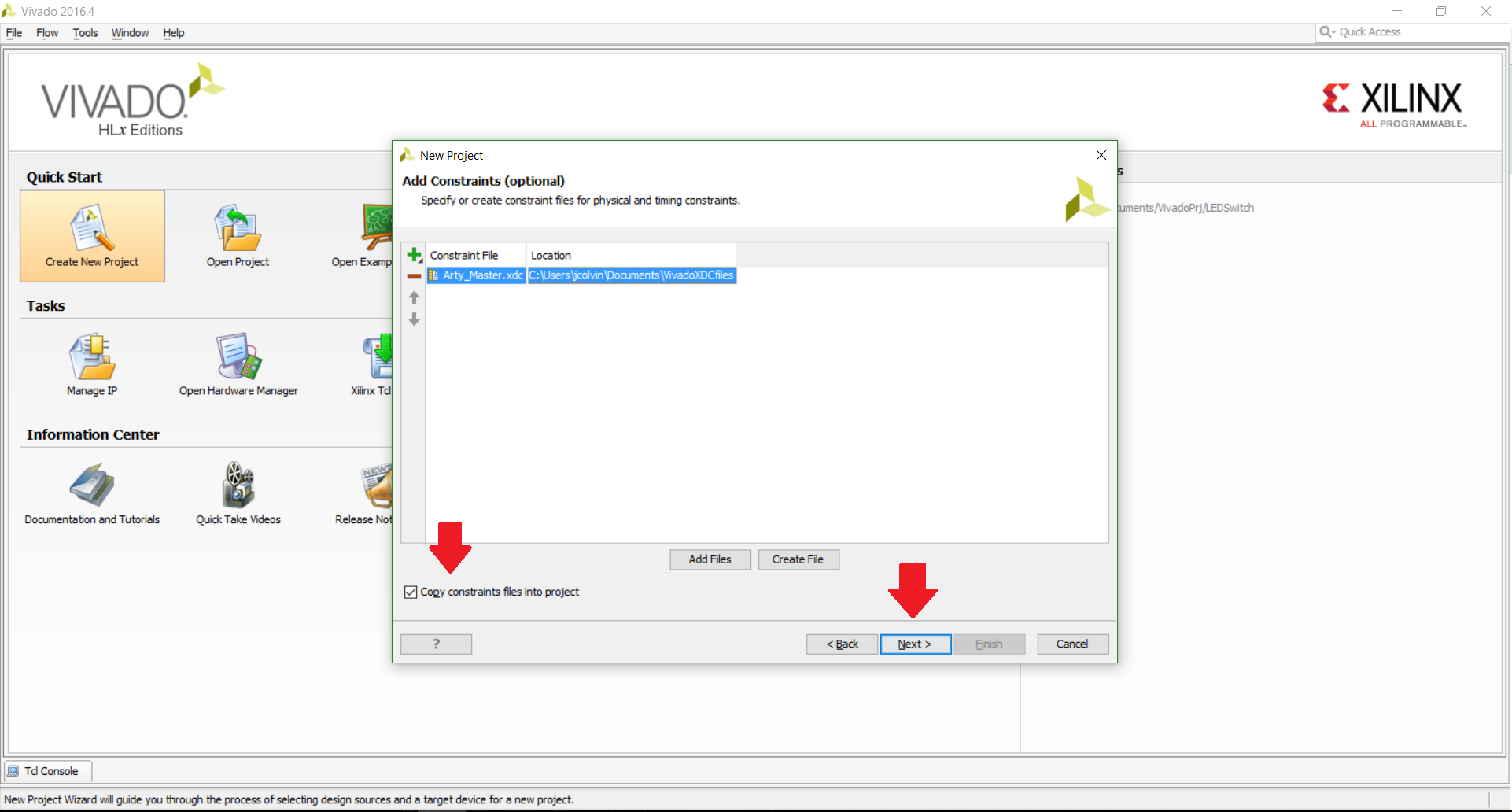
Go ahead and click “Next” on the page asking about IP cores since we don’t have any to add for this tutorials. On the next page for Add Constraints, we will want to choose to “Add Files”; the file we are looking for is the Master XDC file that we added in the previous tutorial. Once you have found and chosen this file, be sure to check the “Copy constraints files into project” box is checked so that the original file does not get altered when we change it later on in the tutorial series. Click “Next”.
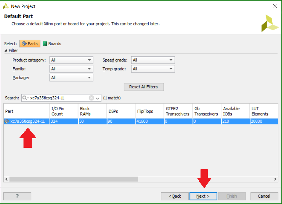
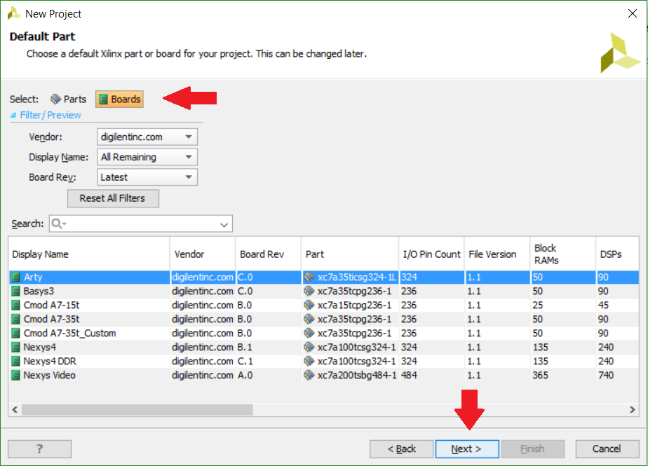
Now we’ll need to select the FPGA that we are using; there are two different ways that we can approach this. We can either manually search for the part (you can find the FPGA part on Digilent FPGA boards by looking their respective Resource Centers underneath the “Documentation” section on the right hand side of the page). Alternatively, if you click on the “Boards” button and you have added in the board file for your respective board (like I did for the Arty board in the previous tutorial), you will be able to easily find your board in the list that appears when you select blog.digilentinc.com as the vendor.
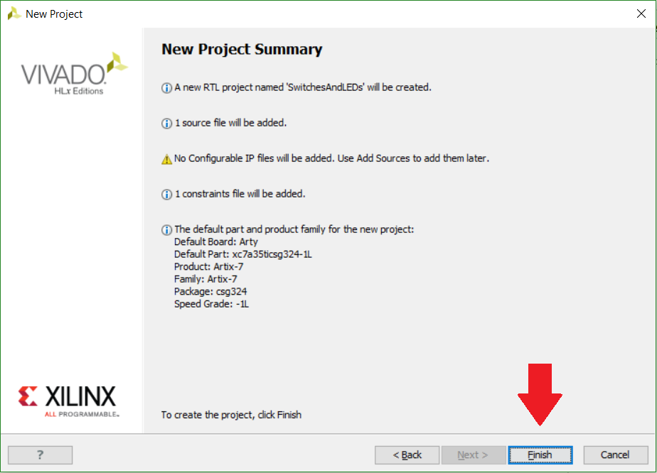
After clicking “Next” after choosing our FPGA board, we will be presented with a final confirmation screen of our new project that we’re about to create. If you’re happy with the summary, go ahead and choose “Finish”.
Great! We’ve gotten through the initial setup of our project and will now be ready to edit our Verilog module and XDC file to suit our project needs. Stay tuned for the next post in this tutorial series! Additionally check out our Wiki for more resources on this project.
One Comment on “Creating and Programming our First FPGA Project Part 2: Initial Project Creation”