
I recently compiled and posted a project on hackster.com describing how a Theremin (an electronic musical instrument) can be built using the Analog Discovery 2, the Digilent Analog Parts Kit, and a beverage can. It was a super fun project, I learned a lot, and it can be found here: https://www.hackster.io/ian-etheridge/beverage-can-theremin-03ba2e
One of the last stages I referred to as an “Envelope Detector.” This stage is a very simple circuit consisting of one diode, one capacitor, and one resistor. These 3 amigos convert a “multi-frequency” input signal, called a modulated signal, into a single-frequency output signal. Here is an example schematic for an envelope detector:
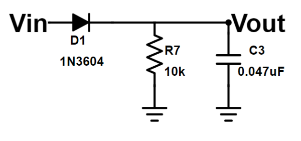
The input signal is a sum of two periodic signals. This is part of how the Theremin and its player can create a signal with varying frequency (visit my project page for more information on this). The “envelope” of a signal can be thought of as the outline if you created a new wave by connecting all the amplitude peaks. When these two summed signals differ in frequency, the resulting signal has a periodic envelope.
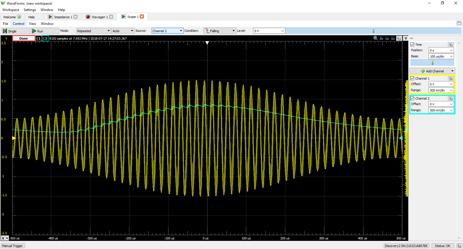
Taking this one step at a time, the diode in this circuit is also called a rectifier. When an alternating signal is presented to a diode, the diode only conducts a signal when the voltage at its anode is positive and provides a potential difference to the cathode, greater than its threshold voltage. This “removes” all negative voltages like its going out of style. If we consider this circuit without the capacitor and keep some arbitrary resistor to complete the circuit, we get rectified! Below is an example of half-wave rectification using our circuit without the capacitor. The yellow signal is the modulated signal from the Analog Discovery 2 Wavegen using the Modulation option. The blue(ish) signal is the rectified output from the diode. Notice how all those pesky negative voltages are gone!
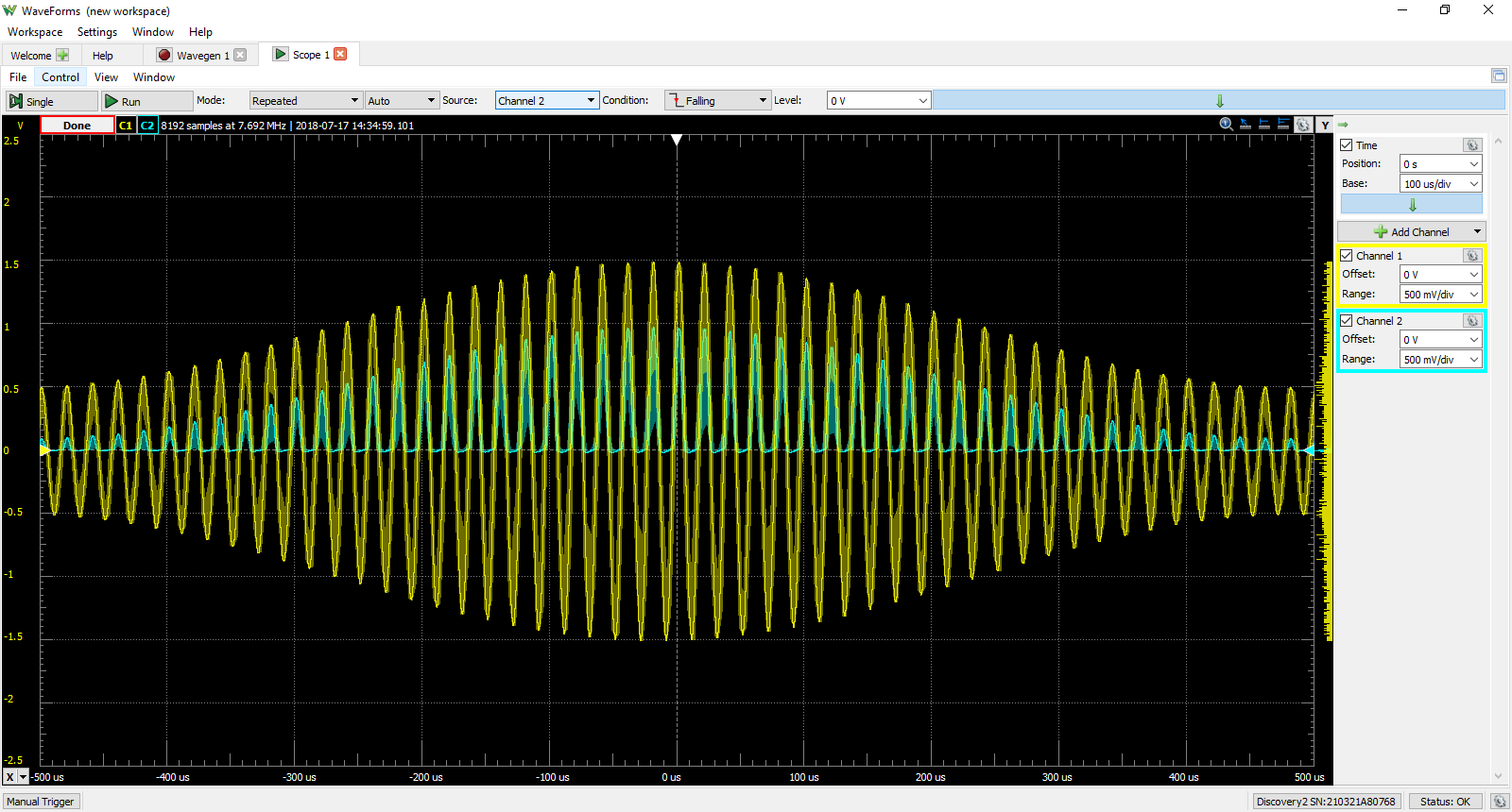
Now let us bring our capacitor buddy back into the picture. The increasing voltage from the rectified signal charges the capacitor. When the voltage begins to drop, the capacitor will start to discharge through the resistor. However, the rate at which the capacitor discharges is (ideally) very much slower than the frequency of the modulated signal. Therefore, the capacitor does not fully discharge on the falling edge of the rectified signal, but will be charged relative to the rectified signal peak amplitudes. The capacitor and resistor together are also a Low Pass Filter, a match made in heaven. The Low Pass Filter smooths out the resulting signal and filters out high frequency noise that is inherently carried by the modulated input signal. Below is an example of our Envelope Detector in action! The yellow signal is the same modulated signal from the previous figure and the blue(ish) signal is now the envelope of the modulated signal (well, at least the shape, in theory the envelope should be “riding” along the peaks of the modulated signal).
This process is also called “demodulation” and was first widely used in AM radio frequency transmission. A baseband signal is modulated (or “added”) to a carrier frequency for transmission. The rectification and filtering takes place at the user end inside the radio, providing the listener with the original broadcast signal. Kick out the jams mother…boards! Changing the resistor and capacitor values would change the time constant and cutoff frequency of the filter, which may be helpful in improving the envelope detection or noise reduction.
AM stands for Amplitude Modulation, demonstrated in our scope shots as the yellow wave. The carrier signal is added to the baseband signal, resulting in a transmittable signal with a frequency of the carrier and varying amplitude that conforms to the baseband signal. Unfortunately, high frequency noise is an inherent problem with AM signals. Now, Frequency Modulation (FM) is more commonly used for higher quality audio transmission as the effects of noise are much less prominent. I found a website dedicated to transistor radio repair that has some great information about AM and FM circuits in application and a great diagram that compares AM and FM signals, respectively. A link to the website is provided below the image.
For reference visit: https://www.vintage-radio.com/repair-restore-information/transistor_vhf-sets.html
Hi ,
Thanks for your nice article.
How to implement enevlope detection by FPGA?
Thanks
Hi Ahmed, and thanks for reading! I found an interesting resource on the Mathworks website using two methods to digitally implement envelope detection using MATLAB. One involves squaring the input signal then applying a low pass filter, the other using a Hilbert transform. Maybe this resource can give you some insight to implementation on an FPGA: https://www.mathworks.com/help/dsp/examples/envelope-detection.html
“A baseband signal is modulated (or “added”) to a carrier frequency for transmission.”
For anyone wondering, the sense in which the baseband signal is “added” to the carrier is not simple addition as the word “added” implies; but rather, multiplication. That’s probably why it was put in quotation marks here. True: it is being “added” in the sense that it is injected into the signal in some unspecified way, but mathematically, you can’t get there by simple addition. Modulation requires/means multiplication. I can explain a bit further for anyone interested (skip this otherwise)….
In this context, modulating a signal by another is essentially multiplying them together. The operation (multiplication) is also commutative so that you can say you are multiplying the other by the one instead of one by the other. However, to get the desired result on the receiving end, you probably need to treat them slightly differently: the modulating signal is usually given a DC offset so that it is always positive (or negative) rather than changing sign. Changing sign in this case would be bad in that the product will have a copy of the carrier wave (still amplitude-modulated) that is now inverted, and that inversion is not normally detected or accounted for in a receiving circuit. The receiving circuit essentially gets the original modulating signal multiplied by itself.
If you were to modulate any signal by itself, all the negatives become positives and you end up with the frequencies doubled (and with a DC offset) — it is similar to rectification itself (which is more like taking absolute value) but is more like a “pure” doubling of frequency because the operation is “smooth” (whereas rectification creates nasty discontinuities at the zero crossings that essentially make up lots of other harmonics besides the 2nd). Imagine a pure sine wave, or better yet, use a graphing calculator, then multiply it by itself, and you can see quite easily that you end up with another pure sine wave at twice the frequency, but all on the positive side.
Caveat: this is not my field of expertise, but my understanding is that we usually say the carrier (the high frequency that remains stable in AM transmission) is modulated in its amplitude by the other, varying signal, but mathematically it works both ways — the only real difference is that you might want to add a DC offset to the modulating signal so that it is always “positive”, thus changing the amplitude of the carrier (upon multiplication) without inverting (negating) it, which allows the simplest tuning circuit to receive the intended signal by low-pass-filtering a rectified version as described (i.e., an envelope follower), without unwanted harmonic distortion (which is what you would get without a DC offset to the modulating signal, due to the rectification used in the receiver).
However, if you are building an oscillator for a synthesizer and decide to employ some amplitude-modulation, then getting some second harmonics due to insufficiently DC-setting the modulating signal might end up being a good thing, if it happens to sound good. 🙂
Anyway, I just wanted to mention that there is multiplication going on here instead of addition. Sorry I got carried away. Back to work, now…
(Sorry, all my paragraph breaks disappeared. Here is a demo of the effect I was trying to describe: https://www.desmos.com/calculator/2wtkqppth1 .)