
Breadboards make the life of any person playing with electronics so much easier. Not only that, but they make everyday things like phones and robots actually possible. I guess maybe robots aren’t everyday things for many people, but you get the idea.
This little tool may take a minute to get the hang of, but it is invaluable when working with electronics. I had never used a breadboard until I started working here at Digilent. I was handed one on my first day and my first thought was “where do I put the wires…?” … “what…what is this?”
(I felt like a robot trying to eat food. source: http://cdn.foodbeast.com.s3.amazonaws.com/content/wp-content/uploads/2011/07/robot-hardees-carls-jr.jpg)
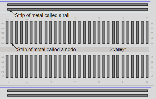
Well fear not newbies! We’re going to summarize the main information about getting started with breadboard. To start, most breadboards are labeled pretty similarly. The rows are numbered and the columns should be labeled with letters.
The rows are linked together by little metal clips. These allow for jumper wires and components (resistor, etc.) to be easily connected, but keeps them from easily falling out.
Along the sides there should be columns marked blue (-) and red (+). Blue represents the ground bus and red is the high voltage bus. If you supply power to any spot on the red side of the column, every hole in the column now has voltage. Similarly, if you do this with ground, the entire column will be what we call a “bus” (i.e. all the holes in the column are ground).
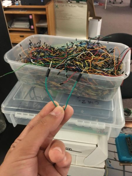
These are great for spreading voltage. Jumper wires help transfer voltage or ground to any place else on the board. Connect a jumper from the high voltage bus on the edge to a single hole anywhere else on the board and voila! That row now has voltage.
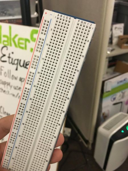
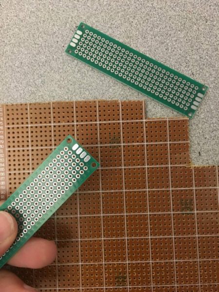
There are two major types of breadboards; these are solder and solderless boards. Solder boards are boards you have to solder components onto (per the name). These are most of your standard circuit boards, and if you flip one over you’ll notice that all of the connections are soldered to the board itself. Solder-less breadboards are the one’s we’ve been focusing on. They make it easy to add or take off components as needed, and make circuit trial-and-error a lot easier. Both types of boards can be large, small… really any size.
The components that work with a breadboard are plentiful too! Resistors, potentiometers, capacitors, inductors, diodes, LEDs, transistors, MOSFETs, thermistors, photocell, buzzers, push buttons, and a whole lot more.
But sometimes, your circuit just doesn’t work and you are forced to ask yourself and possibly anyone in the near vicinity – what the heck is happening? Troubleshooting can be an arduous process sometimes, but knowing some common mistakes might make it easier. If your LED isn’t lighting up or your servo is sitting like a ton of bricks, make sure your connections are hooked into the right row. The breadboard has numbered rows for a reason, and it’s a super helpful way to make troubleshooting go a lot smoother. Make sure your jumper wires and all your connections are pushed in all the way – this is especially important if you’re using a solderless breadboard, and sometimes it can be harder to tell.
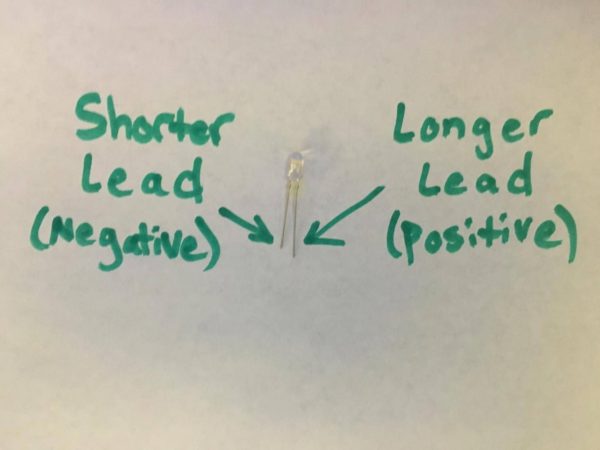
Pay attention to directions as well. For LEDs, the long lead is the anode (positive) and the short lead is the cathode (negative).
And be mindful of short circuits. If you have two leads touching each other on your board, you may have a short circuit. In this case, there is almost no resistance and voltage is essentially free to flow. This can cause overheating, fires, and explosions. So avoid these, if possible.

If you are looking for additional ways to troubleshoot your project also feel free to use a digital multimeter! This acts a great tool when continuity, DC voltages, currents, resistance need to be checked. Additionally the Analog Discovery 2 acts as a great way to analyze circuits, especially with the Logic Analyzer in WaveForms 2015. If your still not sure which tool to use, check out a comparison guide regarding digital multimeters and the Analog Discovery 2 as debugging tools. If your circuit isn’t working and you have the AD2 in your pocket, there’s nothing to fear!
Very interesting read ! Quick question .. does anyone know the difference between Rheostats and Potentiometers ? I only found this article https://www.derf.com/rheostat-overview-article-and-video-explanation/ which explains a bit but not in detail. I still don’t understand what the main differences are…
Anyone help would be appreciated !
‘Rheostat’ is an old term used for a variable resistance, usually in the context of controlling something, like a motor or a light. They were frequently wirewound (literally – resistance wire wound round a circular former, with a wiping contact that formed the variable bit. )
Generally, the term used these days is ‘variable resistor’ but the abbreviation ‘pot’ – short for ‘potentiometer’ is often used too. Strictly, a potentiometer is a variable resistance where one end of the resistance is at some voltage (such as supply volts) and the other is at some other voltage (typically 0V, – also known a s ‘ground’) and then as the wiper of the pot is moved by rotating the knob, a variable voltage (potential – hence potetiometer) which has a value between those two values is produced.
Anyway – if someone talks about a ‘Rheostat’ they are almost certainly of an older generation, and if you mentally substitute ‘variable resistance, probably used to give a varying voltage’ you won’t go too far wrong.